Pre-Charge Relay Repair procedures
Removal
Shut off the High Voltage circuit.
(Refer to Hybrid Control System - “High Voltage Shutoff Procedure”)
Remove the power relay assembly.
(Refer to High Voltage Battery System - "Power Relay Assembly (PRA)")
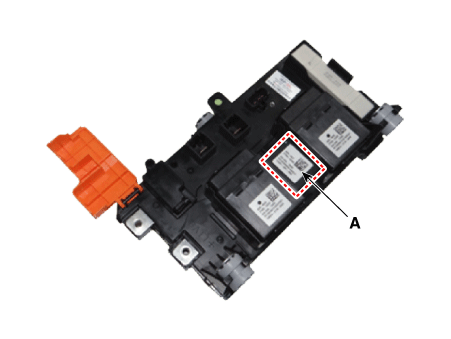
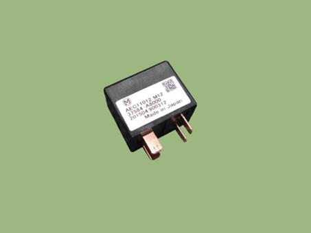
Remove the pre-charge relay (A).
Inspection
High voltage pre-charge relay switch resistance
[Use multi-tester (relay OFF)]
Shut off the high voltage circuit.
(Refer to Hybrid Control System - “High Voltage Shutoff Procedure”)
Remove the rear seat cushion.
(Refer to Body - "Rear Seat Assembly")
Remove the rear door scuff trim.
(Refer to Body - "Door Scuff Trim")
Remove the inlet cooling duct.
(Refer to High Voltage Battery Cooling System - "Cooling Duct")
Measure the resistance between the high voltage power terminal (+) and the inverter power terminal (+).
Specification : ∞Ω[20 °C]
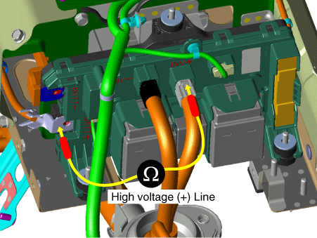

If the measured resistance is not within the specification, replace the main relay (-) by referring to repair procedures.
[KDS/GDS - relay ON]
Connect the KDS/GDS to the Data Link Connector (DLC).
Switch "ON" the ignition.
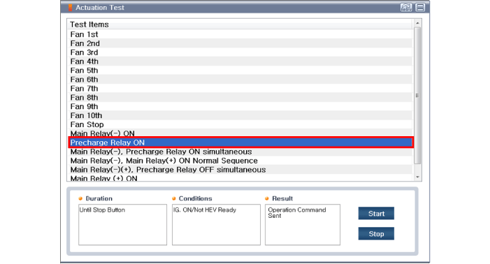
Activate the pre-charge relay by selecting "Actuation Test" on the KDS/GDS as shown in the illustration below.
High Voltage Per-Charge Relay Coil Resistance
Shut off the high voltage.
(Refer to "High Voltage Shut-off Procedures")
Remove the power relay assembly.
(High Battery System - "Power Relay Assembly")
Check for continuity between the terminals using an ohmmeter.
Specification : 57 - 63 Ω [20 °C]

Installation
Install the main relay in the reverse order of removal.