Emission Control System
Schematic Diagrams
In this manual: Emission Control System
15steps
~90min
4/5difficulty
Done 0 of 15
Schematic Diagram
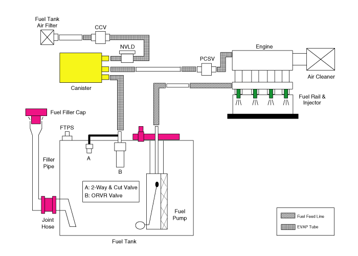
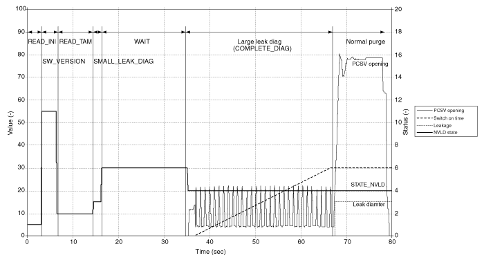
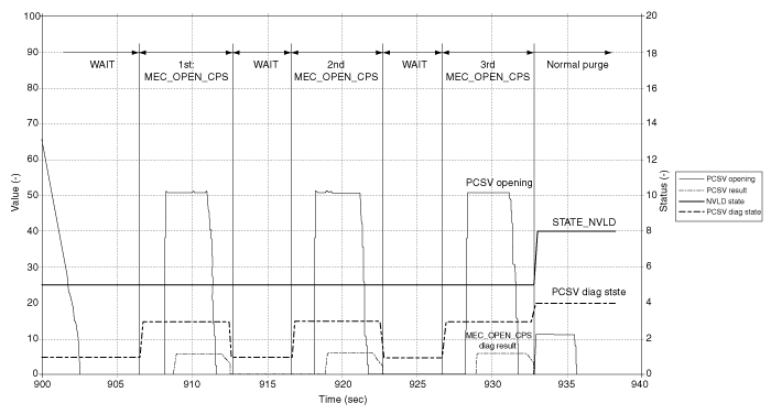
- Read Information (READ_INI and INI): Ready to start diagnosis with initialization. Diagnosis starts with the driver's request to start the vehicle (key position at start). When the process begins, the ECM reads the NVLD information and the malfunction information that is stored while the vehicle key is off. The valid air temperature measurement range is from -40°C to 120 °C. "Out of range" is reported if the measured temperature is outside this range. After the request, read the stored values from the NVLD. The following information is received from the NVLD module: air temperature deviation of 6°C for at least 2 hours during soak, check of NVLD switch closed during soak, air temperature sensor plausibility/electrical fault check detected during soak, pressure switch electrical fault check during soak, and reset of malfunctions due to loss of power.
- Read Information (SW_VERSION): The NVLD sends an 8-bit software version value when the ECM makes a request.
- Read Air Temperature (TAM_SWI_DIAG/READ_TAM): When the ECM requests the air temperature from the NVLD, the measured temperature value is sent to the HCU as an 8-bit value. In case of an "out of range" error, maximum or minimum values are received. During the period whenever the ECM requests the NVLD pressure switch electrical check, the NVLD returns the current and actual values due to the electrical switch error. Because the values from the NVLD may return more than one electrical error at the same time, all errors could have occurred during the engine start phase.
- Small Leak Diagnosis (SMALL_LEAK_DIAG): To check for a small leak, the ECM requests the stored information from the NVLD. During soak, the permitted switch closing time is 10 minutes. This means the maximum time can be 2.5 hours (15 × 10 minutes). The switch closing time is transmitted to the ECM.
- WAIT: Delay time to wait for the next process.
- Large Leak Diagnosis (COMPLETE_DIAG) In this process, the ECM checks for a large leak using the switch check position. During large leak diagnosis, the ECM requests the switch position information, which includes the current switch position and the switch position transition monitored since engine start.
- PCSV Plausibility Diagnosis (CPS_CHK) When a large leak error is detected or the switch is closed at engine start-up, the purge control solenoid valve (PCSV) sticking diagnosis is performed by opening the PCSV.
- STOP When all diagnosis is completed, the ECM requests the STOP status. During this period, whenever the ECM requests the NVLD electrical switching check, the NVLD returns the current and actual values for electrical switching errors until the end of the drive cycle.
- ERROR When any error occurs that prevents continued EVAP monitoring, the ERROR status is set.
- OFF When the engine is off with the ignition off, the ECM requests the OFF status. The NVLD is reactivated by a wake-up call at the next drive cycle (ignition switch ON). During this period, the NVLD checks the timer function and reports a malfunction if any problem is detected.
- SLEEP If the key-off monitoring conditions for small leak detection are not satisfied, the ECM requests the SLEEP status. No calculations are performed in the NVLD during the key-off period in the SLEEP status.
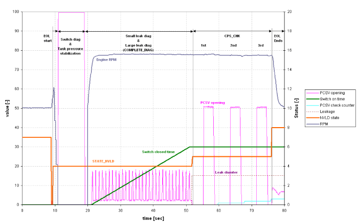
- Switch Check and Tank Pressure Stabilization To perform the NVLD leak diagnosis, the ECM software skips the normal process and starts the diagnosis immediately after leak diagnosis requests. When leak diagnosis is requested by the external scan tool, the ECM requests the HCU to stop the engine. When the engine stops, the ECM fully opens the PCSV to check the NVLD pressure switch for sticking and to stabilize the tank pressure before starting leak diagnosis. If any switch sticking fault is detected, the leak diagnosis is terminated and the result is reported through the scan tool.
- Small and Large Leak Diagnosis After the switch sticking check and pressure stabilization, the ECM requests the HCU to start the engine, with an idle target speed of 1500 rpm for stability. The ECM opens the PCSV and checks the NVLD pressure switch position while the switch is closed. The longer the switch closed time, the larger the leak size that can be estimated. The ECM converts the switch closed time into leak size and reports the result. If no leak is detected or a small leak is detected, the leak check diagnosis is terminated. However, if a large leak fault is detected, the process proceeds to the next step.
- PCSV Plausibility Diagnosis When any large leak is detected in the previous state, the ECM performs the PCSV sticking diagnosis to check the root cause of the increased leak. The ECM opens the PCSV and checks the diagnosis results. If the diagnosis results are acceptable, the ECM ends the leak diagnosis and confirms the large leak fault is not present. However, if the results are out of range, the ECM attempts the PCSV plausibility diagnosis up to 3 times. When the results are still unsatisfactory after 3 tests, the ECM confirms PCSV sticking and reports the result.
- Leak Diagnosis Cancellation If any condition is not satisfied, the ECM stops the process and reports the cancellation reason through the scan tool. The engineer can check the root cause and resolve the problem to restart the process.
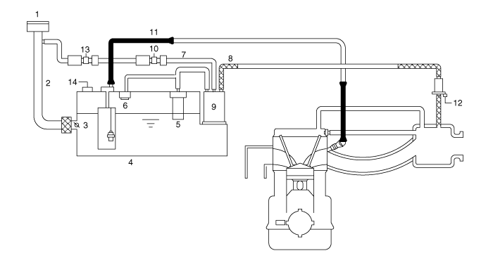
| 1. Fuel Tank Cap 2. Filler Neck 3. Fuel Cut-Off Valve 4. Fuel Tank 5. ORVR Valve 6. 2-Way and Roll-Over Valve 7. Evaporative Hose |
8. Evaporation Hose 9. Canister 10. Natural Vacuum Leak Detection Module (NVLD) 11. Fuel Feed Line 12. Purge Control Solenoid Valve (PCSV) 13. Canister Close Valve (CCV) 14. Fuel Tank Pressure Sensor (FTPS) |
Test yourself
A quick Kia Optima Hybrid Owner's Manual quiz: every answer comes with an explanation and a link to the manual page.
Was this page helpful?