Suspension System
TPMS Sensor Description and Operation
In this manual: Suspension System
9steps
~54min
2/5difficulty
Done 0 of 9
Description
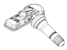
Operation Mode
ASIC Mode
- Factory Mode. Factory mode allows the TPM sensor to transmit RF frames more often and to sample LF at the HKMC factory. The trusted platform module sensor will send normal RF frames in factory mode. LF sampling occurs every 1 second to ensure a fast response on the production line. Figure 5 shows the ASIC state flow from Off mode through Factory mode to Non-Factory mode. Factory mode is not a normal mode; it operates on top of other customer visibility modes to increase LF sampling rate while the factory counter is non-zero. When exiting Off mode, the factory counter is set to 15. Each time the sensor transitions from service mode to stationary mode, the counter is decremented. After the Factory mode expires, the Factory_LF command can be used to re-enter Factory mode, in which case the factory counter is reset to 15. If Factory mode is no longer required, the factory counter can be reset and therefore exit Factory mode using the Exit_Factory_LF command. In the 10.8 s mode, the sensor transmits normal RF frames every 10.8 s. In the case of a high-line sensor, the function code indicates the direction of rotation.
Mode Pressure Sampling Rate (seconds) Temperature Sampling Rate (seconds) Sampling Rate When Rotation Is Detected (seconds) Normal Transmission Rate (seconds) Plant 10,8 10,8 10,8 10,8 - Stationary Mode. In normal operation and when the vehicle is not moving, the TPM sensor is in STATIONARY mode. In this mode, the sampling and transmission rates are described below.
Mode Pressure Sampling Rate (seconds) Temperature Sampling Rate (seconds) Sampling Rate When Rotation Is Detected (seconds) Normal Transmission Rate (seconds) Non-Factory 60 60 15 - Plant 60 60 15 -
STATIONARY mode is activated when the vehicle starts moving and the shock sensor input signal is checked by the ASIC. - AL/ALO Mode. When rotation is detected, the Unknown/Normal function code is transmitted, and the sensor enters AL (Auto Learn) mode or ALO (Auto Location) mode, depending on the TPM sensor type (Lowline or Highline). In AL mode, the sensor continues to transmit Unknown/Normal function codes every 33 seconds for 16 RF blocks (1 RF block = 4 RF frames). In ALO mode, the TPM sensor begins determining the rotation direction of the sensor, clockwise or counterclockwise. For the first transmission after the Unknown/Normal function code, the data block will contain one of three function codes for ALO mode. If the ASIC cannot determine the rotation direction, the sensor must transmit the Unknown/Normal function code. In AL/ALO mode, the shock sensors are polled for motion every 10.8 seconds. Pressure and temperature samples are also taken every 10.8 seconds. The transmission rate and duration of AL/ALO mode set the transmission rate of one block (4 frames) every 33 seconds for a duration of 16 blocks. In ALO mode, the rotation direction is determined every 10.8 seconds. The transmitted function code is based on all ALO data since the last transmission. The AL/ALO mode function flag is set to transmit all valid AL/ALO frames. If the vehicle speed drops below the stationary threshold and the sensor detects no motion, then the sensor exits AL/ALO mode and enters service mode. If service mode is exited due to detection of motion, AL/ALO mode is re-entered. AL/ALO mode continues from where it was stopped, i.e., the 16-block duration is reached regardless of service or alert mode. The mode was entered during this AL/ALO mode. If a pressure change is detected in AL/ALO mode (alert mode) and DP transmissions occur, AL/ALO mode is suspended until the DP transmissions are completed. Sensors with ALO mode have 4 configurable parameters for optimizing WAL performance based on customer evaluation. Sensors for Hyundai/Kia are configured to option 2.
Mode Pressure Sampling Rate (seconds) Temperature Sampling Rate (seconds) Sampling Rate When Rotation Is Detected (seconds) Normal Transmission Rate (seconds) Non-Factory 10,8 10,8 10,8 33 Plant 10,8 10,8 10,8 33 - Service Mode. Service mode is the period when the TPM sensor has detected that the vehicle speed has dropped below the stationary threshold. During this period, pressure, temperature and motion measurements are taken every 15 seconds, but there is no transmission; the TPM sensor will transmit only when a pressure change (DP) is detected. The DP transmission consists of two blocks (8 frames in total) of transmitted pressure information over a two-second period. The duration of service mode is 15 minutes from the moment the TPM sensor detected no rotation. If rotation is detected again in service mode, the sensor exits service mode and returns to the mode it was in before entering service mode, AL or normal mode. Each time service mode is entered, the 15-minute timer is reset. If service mode is exited before the service mode timer expires, the mode counter is not reset. Upon expiration of service mode, the mode counter is reset.
Mode Pressure Sampling Rate (seconds) Temperature Sampling Rate (seconds) Sampling Rate When Rotation Is Detected (seconds) Normal Transmission Rate (seconds) Non-Factory 15 15 15 - Plant 15 15 15 - - Rolling Mode. When the AL mode expires, the TPM sensor switches to Rolling Mode. In Rolling Mode, the transmission rate and the rolling detection sampling are reduced to once every 60 s, and the pressure and temperature sampling occurs every 15 seconds. For the first 16 transmissions after the start of movement, the TPM sensor transmits AL mode function codes: Clockwise, Counterclockwise, or Normal/Unknown. After 16 AL information transmissions have been sent, the TPM sensor will transmit the Normal/Unknown function code. If the vehicle speed drops below the stationary threshold and the TPM sensor detects that no rolling detection is present, then Rolling Mode will be suspended and Service Mode will be entered. When entering Rolling Mode, the TPM sensor measures the pressure and performs a normal radio transmission with the NORMAL/UNKNOWN function code (see 4.1.1.5: Status Byte).
Mode Pressure Sampling Rate (seconds) Temperature Sampling Rate (seconds) Sampling Rate When Rotation Is Detected (seconds) Normal Transmission Rate (seconds) Non-Factory 15 15 60 60 Plant 15 15 60 60
When the vehicle speed drops below the minimum vehicle speed threshold, the sensor remains in Rolling Mode until the next scheduled rolling detection sample occurs. Once the rolling detection sample confirms that the vehicle speed is below the threshold, the TPM sensor will enter Service Mode. After the Service Mode period expires, the TPM sensor will enter STATIONARY mode. - Alert Mode. In Stationary Mode, Service Mode, or Rolling Mode, pressure is measured at the intervals described above. During each measurement, the current pressure value is compared with the previously transmitted pressure value. If the current pressure sample differs by more than 8 counts (> 2 psi) from the previously transmitted pressure value, a RE-MEASURE will occur immediately to confirm that the sample is correct. If the delta P is confirmed, the TPM sensor will transmit immediately with the Alert status code. If a RE-MEASURE transmission coincides with a normal transmission, the RE-MEASURE has priority and the normal transmission will be replaced by the RE-MEASURE transmission.
- Stationary Alert Mode. While the sensor is in Stationary Mode, it must transmit an instantaneous measured data frame, as defined in Section 4.1 of this document, if the pressure changes by 2.0 psi or more since the last transmission. All transmissions due to a pressure change event must carry the Alert status code, as specified in Section 4.1.1.5.6. Stationary Alert Mode will be disabled if a pressure change of 2.0 psi or more is not detected after 2 consecutive samples.
Pressure Sampling Rate (seconds) Temperature Sampling Rate (seconds) Sampling Rate When Rotation Is Detected (seconds) Normal Transmission Rate (seconds) 2 (max.) 2 (max.) N/A ?П - When the sensor is in Rolling Mode, it must transmit an instantaneous measured data frame, as defined in Section 4.1 of this document, if the pressure changes by 2.0 psi or more since the last transmission. All transmissions due to a pressure change event must carry the Alert status code, as specified in Section 4.1.1.5.6. Rolling Alert Mode will be disabled if a pressure change of 2.0 psi or more is not detected after 2 consecutive samples.
Pressure Sampling Rate (seconds) Temperature Sampling Rate (seconds) Sampling Rate When Rotation Is Detected (seconds) Normal Transmission Rate (seconds) 2 (max.) 2 (max.) N/A ?П
- Stationary Alert Mode. While the sensor is in Stationary Mode, it must transmit an instantaneous measured data frame, as defined in Section 4.1 of this document, if the pressure changes by 2.0 psi or more since the last transmission. All transmissions due to a pressure change event must carry the Alert status code, as specified in Section 4.1.1.5.6. Stationary Alert Mode will be disabled if a pressure change of 2.0 psi or more is not detected after 2 consecutive samples.
- OFF Mode. This mode is mainly used for shipping and storage of TPM sensor units. When the sensor is de-energized (using the LF Enter_Off command), it must transmit one final transmission with the OFF mode function code, then immediately enter OFF Mode. When the TPM sensor is in OFF Mode, it must continue to sample pressure and temperature at the rate specified in Table 13 of this document, but must not transmit any transmissions until the TPM sensor is re-activated. The TPM sensor can be re-activated by the LF Normal command or by detecting a pressure change of 19 psi or more.
Pressure Sampling Rate (seconds) Temperature Sampling Rate (seconds) Sampling Rate When Rotation Is Detected (seconds) Normal Transmission Rate (seconds) 60 (max.) 60 (max.) - - - RF Test Mode. The sensor must enter RF Test Mode and provide the status code specified in 4.1.1.5.6 of this document when it receives an LF signal with the LF data command "Test_LF" specified in Table 16 below. The sensor must respond (transmit and provide data) no later than 700.0 ms after detecting the LF data code. Once the sensor enters this mode, it must perform all sampling and transmission requirements specified in Table 14 of this document for this specific mode, independent of Rolling, Stationary, or Service Mode. The sensor must count the number of frames (each transmission contains four frames, as shown in Table 15 of this document) it has transmitted since entering this mode, and this number must be transmitted in the data in each frame, as shown in Table 15 below. The transmitted data must be in the format shown in Table 15 below. When the frame count reaches 255 (all 8 bits used), the counter must reset and restart. The sensor clears the frame count when it exits this mode. The sensor must exit this mode upon receiving the Normal_LF command specified in Section 3.3.2 of this document. The sensor must start an eight-hour timer when it enters this mode, and must exit this mode immediately after the eight (8.0) hour timer expires.
Pressure Sampling Rate (seconds) Temperature Sampling Rate (seconds) Sampling Rate When Rotation Is Detected (seconds) Normal Transmission Rate (seconds) 15 (max.) 15 (max.) 15 (max.) 15 (max.)
RF Test Mode Data Structure = Frame 1 = Frame 2 = Frame 3 = Frame 4 Preamble H/L Bit ID Pressure Frame Count Status CRC 16 bits 1 bit 31 bits 8 bits 8 bits 8 bits 8 bits - Continuous Wave (CW) Mode. The TPM sensor must enter the specified CW mode when it receives the corresponding LF data command (CW_Low_LF or CW_High_LF). The TPM sensor must respond (transmit) no later than 200.0 ms after detecting the LF data code. Once the sensor enters this mode, it must begin transmitting at the specified CW frequency (carrier wave frequency) of the TPM sensor. Two CW modes are available:
- CW Low will transmit continuously at the lower FSK frequency.
- CW High will transmit continuously at the upper FSK frequency.
Test yourself
A quick Kia Soul EV Owner's Manual quiz: every answer comes with an explanation and a link to the manual page.
Was this page helpful?