8LR Brake Control Solenoid Valve (8LR/B_VFS)
Specifications
Specifications
| Item | Specification |
| Control Type | N/L (Normally Low) |
| Control Pressure kPa (kgf/cm², psi) | 0–1 569,06 (0–16, 0–227,57) |
| Current (mA) | 0 - 1100 |
| Coil Resistance (Ω) | 5,3 ± 0,3 |
Components and Component Location
Component Location
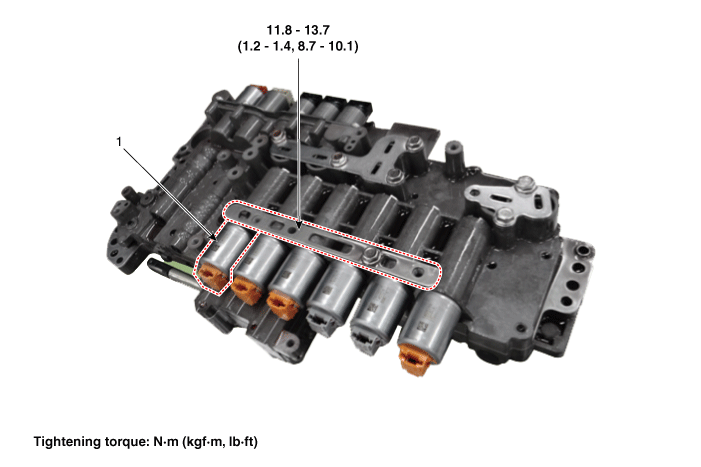
| 1. 8LR Brake Control Solenoid Valve | 2. Solenoid Valve Support Bracket |
Description and Operation
Description
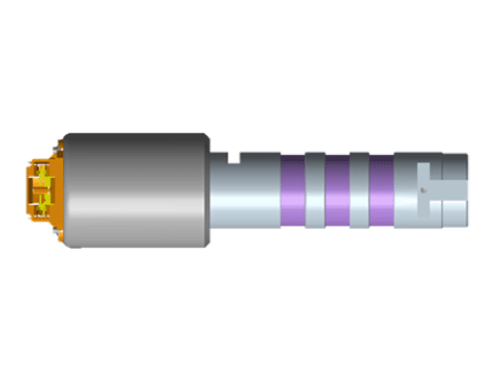
The 8LR brake control solenoid valve is a variable force solenoid (VFS) valve.
When the TCM supplies current to the solenoid valve, the 8LR brake hydraulic pressure is controlled directly by the solenoid valve.
Solenoid Valve Operation Table
| Solenoid valve | Brake | |
| 8LR/B_VFS | 8LR/B | |
| P | ||
| N | ● | ● |
| 1 | ● | ● |
| 2 | ||
| 3 | ||
| 4 | ||
| 5 | ||
| 6 | ||
| 7 | ||
| 8 | ● | ● |
| REV | ● | ● |
Circuit Diagrams
Wiring Diagram
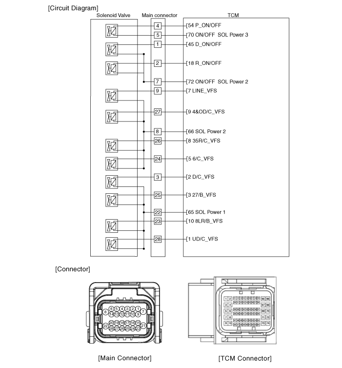
Repair Procedures
Inspection
Turn the ignition switch OFF.
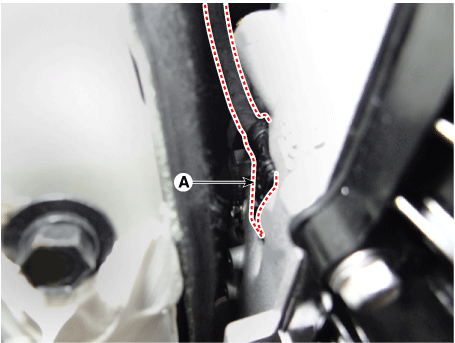
Disconnect the main connector (A).
Measure the resistance between the power terminal (22) and the signal terminal (23).
Specification: 5.3 ± 0.3 Ω
Removal
Remove the under cover.
(Refer to Engine Mechanical System - "Under Hood Compartment").
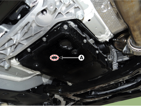
Remove the ATF drain plug (A), allow the fluid to drain, and then reinstall the drain plug.
Tightening torque: 22.6–24 N·m
Disconnect the main connector (A).
Remove the valve body cover.
Loosen all valve body bolts except the bolts (A) at the corner.
Tightening torque: 13.7 - 15.7 N·m
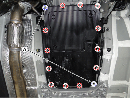
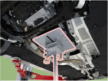
Loosen the two bolts (A) at the corner. After supporting the valve body cover with a jack, remove the valve body cover by lowering the jack slowly.
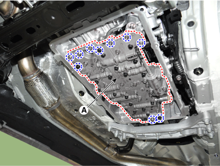
Remove the valve body (A) after loosening the bolts.
Tightening Torque: 9.8–11.8 N·m
Remove the electronic module (A) after loosening the bolts.
Tightening Torque: 9.8–11.8 N·m
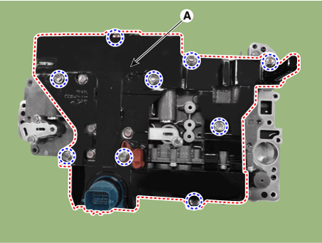
Remove the solenoid valve support bracket (A).
Tightening torque: 11.8–13.7 N·m

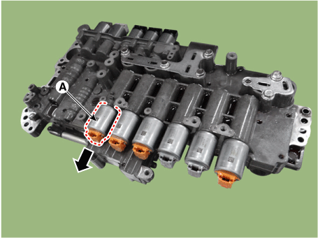
Remove the pin (A).

Remove the 8LR brake control solenoid valve (A).
Installation
Install in the reverse order of removal.
After installation, perform the procedures described below.
Fill the automatic transmission with fluid.
(Refer to Hydraulic System - "Fluid")
Erase the diagnostic trouble codes (DTCs) using the KDS. Disconnecting the negative battery terminal will not erase DTCs. Always use the KDS to erase trouble codes.
Reset the automatic transmission adaptive values using the KDS.

Perform the oil pressure characteristic entry procedure using the KDS.
(Refer to Hydraulic System - "Oil Pressure Characteristic Entry")
Perform the TCM adaptive value learning procedure.
(Refer to Automatic Transmission Control System - "Repair Procedures")
After installation, check for fluid leaks from the hose connection while starting the engine.
Test yourself
A quick Kia Stinger CK quiz: every answer comes with an explanation and a link to the manual page.