Electric Parking Brake (EPB)
Description and Operation
Description
The Electric Parking Brake (EPB) differs from conventional parking systems that operate with a brake pedal or lever type. The EPB system sends a signal to the ECU when the driver presses the EPB switch. The ECU controls the EPB actuator, which consists of geared motors. The braking force is generated when the motor pulls the cable connected to the brake system.
The EPB ECU is one of the components of the EPB system. It receives signals from various system sensors, performs self-diagnosis, and controls the EPB system with logic.
Main Function
Static Braking Mode
Operation and Cancellation when the Vehicle is Stopped
Operating conditions: Pull the EPB switch regardless of the brake pedal condition (Pull).
Vehicle speed <= 3 km/h
Cancellation condition: Press the EPB switch with the ignition switch ON and the brake pedal depressed (Push).
Dynamic Brake Function
Dynamic Brake Function (DBF): The DBF is a braking function under driving conditions. It can control and release the EPB system while the vehicle is being driven. This function is used when the brake pedal or brake hydraulic line cannot operate due to foreign material.
Operating Conditions
It operates only when the vehicle speed exceeds 3 km/h and the EPB switch is pulled.
Cancellation condition: Cancelled when the EPB switch is released.
Principle of Operation
ESP system in normal state: EPB requests are sent. Brake pressure is controlled by the ESP system.
ESP system in abnormal state: EPB controls the parking brake to reduce vehicle speed.
Features
The Anti-lock Brake System (ABS) operates when the wheels lock. The brake warning light on the instrument panel illuminates in case of emergency braking.
Drive-Away Release
For convenience, the EPB is automatically released when the shift lever is moved from P to another position (R/N/D/S) while braking.
Stroke Reset
This is the reconnection function for normal EPB operation after an emergency release.
Operation
After emergency release, when the EPB is applied for the first time, the hook engages with the catch in the EPB with the parking brake applied at maximum cable tension.
The reconnection function can be performed using GDS.
After 5 reconnection attempts, the EPB does not operate in the current ignition cycle. Normally, the EPB does not reconnect.
Bedding-In Mode
You must perform the "Bedding-In Process" to optimize the initial operation performance of the EPB after replacing the parking brake pads and rear brake discs.
Bedding-In Process
Turn the ignition on and start the engine.
Depress the brake pedal 2 times within 10 seconds and hold it depressed after the last application.
Press the EPB switch 4 times, then release it 3 times within 10 seconds.
Pads must be bedded in by repeating the dynamic braking procedure 6 times from 30-35 km/h (19-22 mph) to a complete stop of the vehicle. (If the vehicle speed exceeds 50 km/h in bedding-in mode, it is automatically cancelled.)
A cooling period for the pads is required after each braking cycle to prevent damage to the friction lining.
Cooling can be performed by driving 500 m (1,640 ft) after each braking cycle without applying the EPB, or by holding the vehicle stationary for 1 minute after each braking.
AVH (Auto Vehicle Hold)
AVH maintains the vehicle stopped state using the hydraulic brake.
Operating Conditions
Engine running
Turn AVH on.
Driver door closed
Driver seat belt fastened
The shift lever is not in the P range.
Vehicle stopped condition is maintained when the brake pedal is depressed.
The AVH function maintains the vehicle stopped state for a maximum of 5 minutes.
The VDC valve maintains the stopped state by closing the oil passage when the brake pedal is pressed.
Total AVH operating time: 30 minutes maximum
Automatic Release Function
AVH mode is cancelled when the driver attempts to start the vehicle by depressing the accelerator pedal in D/S/R range.
Automatic Conversion from AVH to EPB
AVH automatically converts to EPB operation if any of the conditions below are met.
[Normal Transition Case]
When the driver door is opened and the driver seat belt is unfastened at the same time
When the hood is opened with the shift lever in D or S
When the trunk is opened with the shift lever in P
When AVH operating time exceeds 5 minutes
Stopped on a 25-degree slope
[Abnormal conversion cases]
When detailed vehicle movement is detected.
When a malfunction of the ESP hydraulic system is detected.
Indicator Lamp
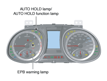
EPB Warning Light
The EPB warning light indicates EPB release and EPB malfunction.
The EPB warning light is located under the cluster.
The EPB warning lamp illuminates for 3 seconds after the ignition switch is turned ON. If the EPB system operates normally, the EPB warning lamp turns off.
If the EPB system does not operate properly, the EPB warning lamp illuminates.
The EPB warning lamp illuminates in diagnostic mode.
AUTO HOLD lamp / AUTO HOLD function lamp
AUTO HOLD ON
A. The brake system operates automatically when the vehicle speed is "0", when parking or waiting at a red light, or during braking (AUTO HOLD function indicator: green).
B. The brake system is released automatically when the accelerator pedal is depressed. (AUTO HOLD indicator: white)
AUTO HOLD switch OFF: The AUTO HOLD function does not operate.
Circuit Diagrams
Wiring Diagram
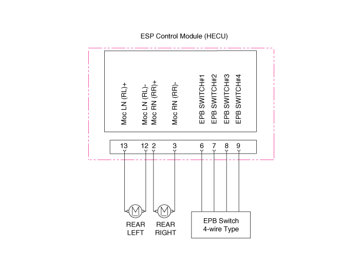
Terminal Function
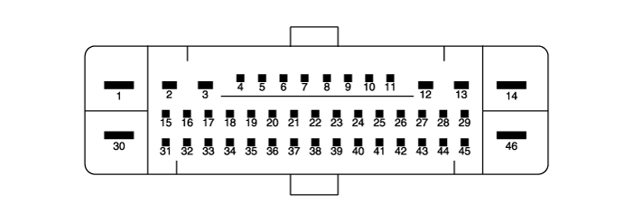
| Pin No. | Function | Pin No. | Function |
| 6 | Electronic Parking Brake Signal 1 | 2 | Rear RH EPB Motor Power |
| 7 | Electronic Parking Brake Signal 2 | 3 | Rear RH EPB Motor Ground |
| 8 | Electronic Parking Brake Signal 3 | 12 | Rear LH EPB Motor Ground |
| 9 | Electronic Parking Brake Signal 4 | 13 | Rear LH EPB Motor Power |
Repair Procedures
Diagnostic Procedure Using a Diagnostic Tool
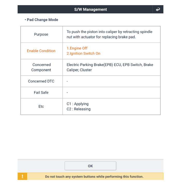
Brake Pad Replacement Mode
Perform the "Brake Pad Replacement Mode" using the KDS, following the procedure below for vehicles with EPB.
Connect the self-diagnosis connector (16-pin) located under the driver's side trim panel to the self-diagnosis device, then turn on the self-diagnosis device after turning the ignition key ON.
Select the "Vehicle Model" and "ABS/VDC" on the KDS vehicle selection screen, then select OK.
Select "Brake Pad Replacement Mode" on the KDS screen, then select OK.
Continue the test according to the instructions on the screen.
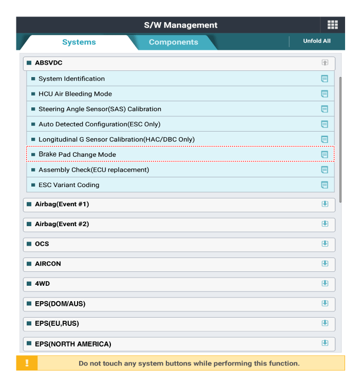
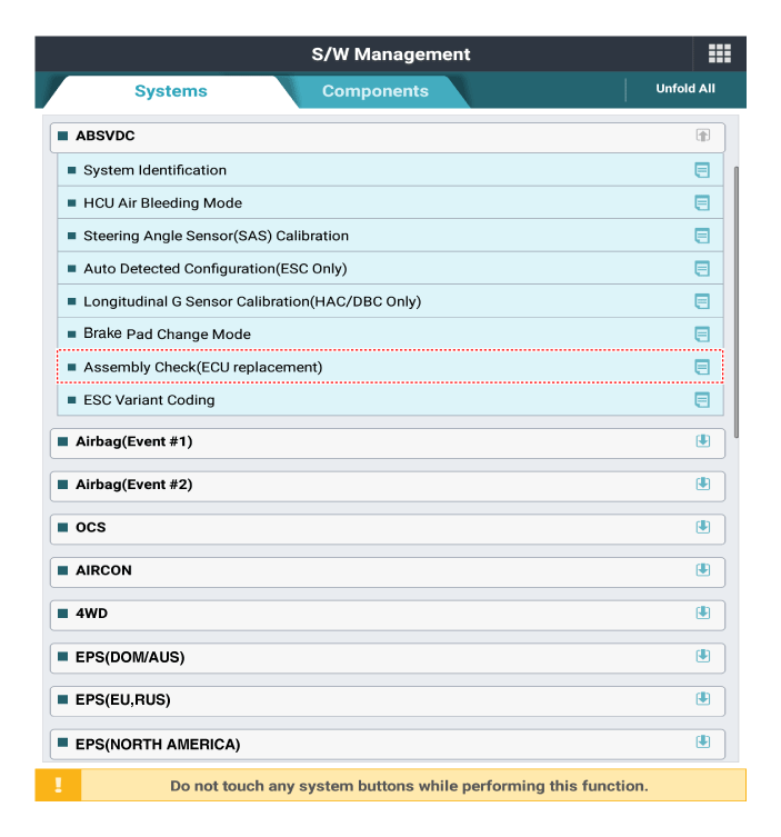
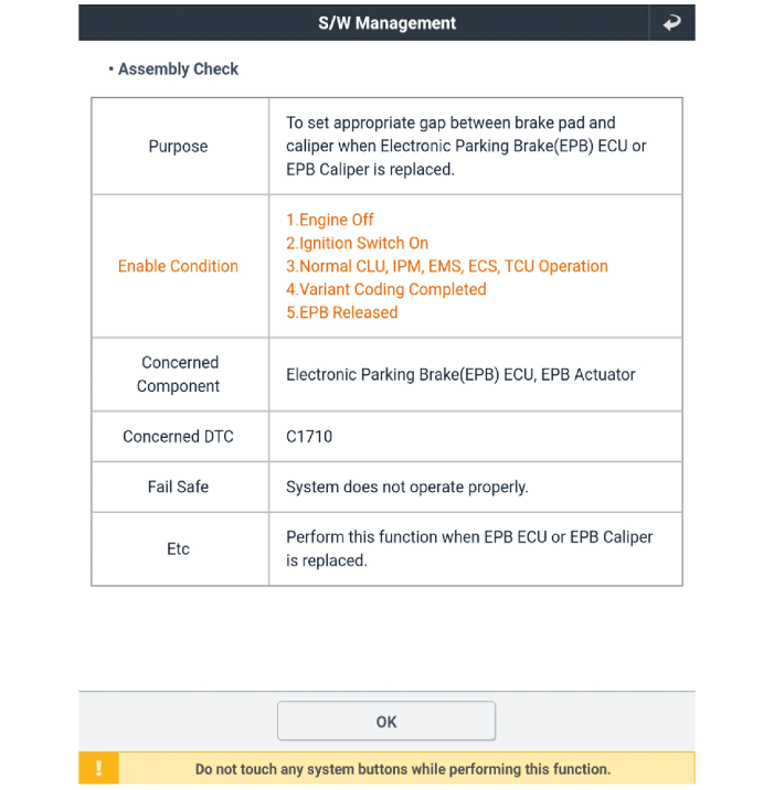
Assembly Check
Perform the "Brake Pad Replacement Mode" using the KDS, following the procedure below for vehicles with EPB.
Connect the self-diagnosis connector (16-pin) located under the driver's side trim panel to the self-diagnosis device, then turn on the self-diagnosis device after turning the ignition key ON.
Select the "Vehicle Model" and "ABS/VDC" on the KDS vehicle selection screen, then select OK.
Select "Assembly Check" on the KDS screen, then select OK.
Continue the test according to the instructions on the screen.
Replacement
[EPB Switch]
Turn the ignition switch OFF and disconnect the negative (-) battery cable.
Remove the floor console upper cover assembly.
(Refer to Body - Floor Console Assembly)
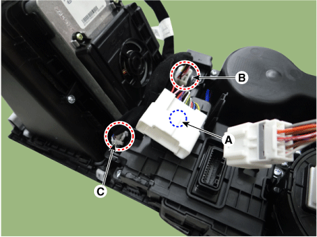
Remove the wireless charging pad (A).
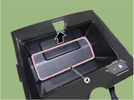
Disconnect the connector, then remove the wireless charging unit.
(A): Main connector mounting
(B): Floor console switch full connector
(C): Wireless charger connector
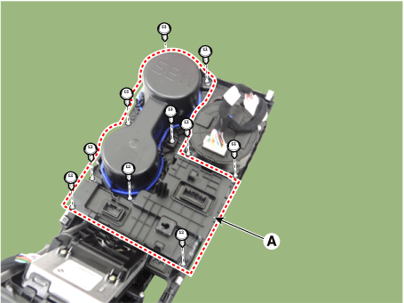
Remove the console cup holder assembly (A) after loosening the screws.
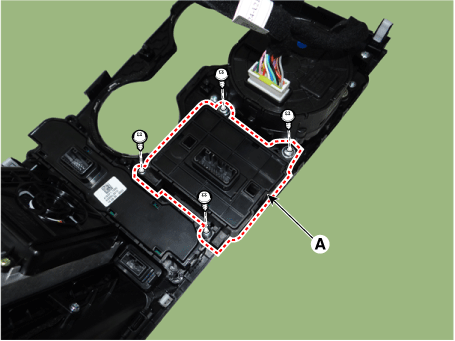
Remove the EPB switch (A) after loosening the screws.
[EPB Actuator]
Turn the ignition switch OFF and disconnect the negative (-) battery cable.
Remove the EPB actuator from the rear caliper.
(Refer to Brake System - "Rear Brake Caliper")
Test yourself
A quick Kia Optima DL3 quiz: every answer comes with an explanation and a link to the manual page.