ESC (Electronic Stability Control) System
Components and Component Location
Components
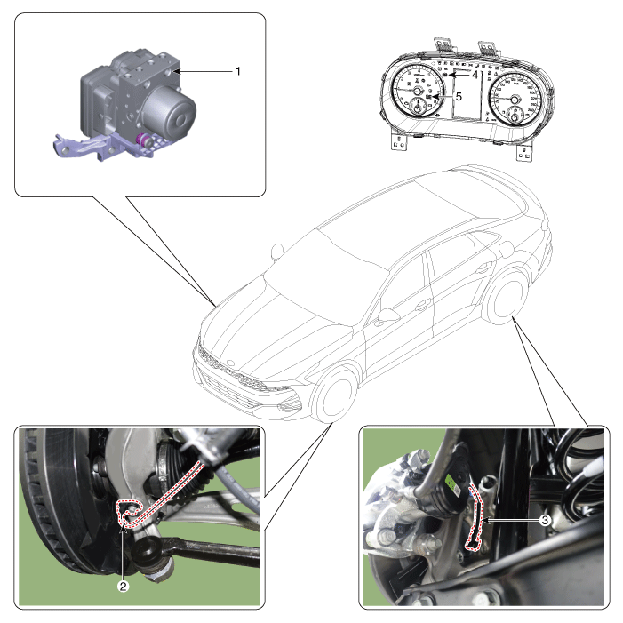
| 1. ESC Control Module (HECU) 2. Front Wheel Speed Sensor 3. Rear Wheel Speed Sensor |
4. ABS Warning Lamp 5. Parking Brake/EBD Warning Lamp |
Description and Operation
ESC Description
Electronic Stability Control (ESC) recognizes critical driving conditions, such as panic reactions in emergency situations, and stabilizes the vehicle by individual wheel braking and engine torque control.
ESC adds an additional function to ABS known as Active Yaw Control (AYC). The functions of TCS, EBD and ESC are closely related. In contrast, the ABS/TCS function controls wheel slip during braking and acceleration and thus mainly intervenes in the longitudinal dynamics of the vehicle, while Active Yaw Control stabilizes the vehicle about its vertical axis.
This is achieved by individually intervening in the wheel brakes and adjusting the instantaneous engine torque without any action required from the driver.
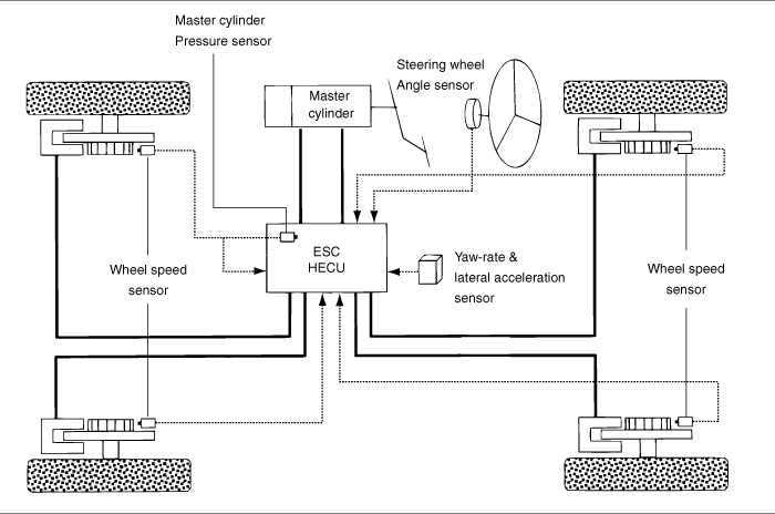
ESC mainly consists of three units: sensors, electronic control unit and actuators.
The stability control function operates under all driving and operating conditions. Under certain driving conditions, the ABS/TCS function may be activated simultaneously with the ESC function in response to driver input.
In the event of a failure of the stability control function, the basic safety function of ABS is still maintained.
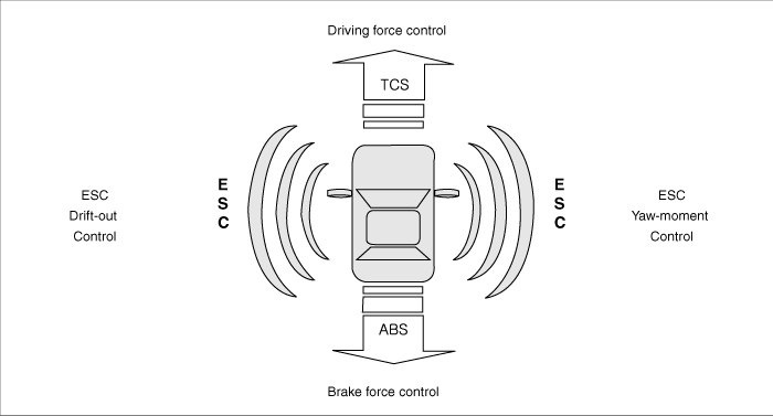
ESC Control Description
The ESC system consists of the ABS/EBD, TCS and AYC functions.
ABS/EBD Function: The ECU converts the active sensor signal (current switching) received from the four wheel sensors into square waves. Using the input of these signals, the ECU calculates the vehicle speed, as well as the acceleration and deceleration of each of the four wheels. The ECU then determines whether to activate ABS/EBD or not.
The TCS function prevents wheel slip in the direction of travel by adding brake pressure and reducing engine torque via the CAN bus. The TCS function uses the wheel speed sensor signal to detect wheel slip before the ABS function.
The AYC function prevents unstable vehicle maneuvering. To determine the vehicle maneuver, the AYC function uses signals from the maneuver sensors (yaw rate sensor, lateral acceleration sensor and steering wheel angle sensor).
If the vehicle maneuver is unstable (oversteer or understeer), the AYC function applies brake pressure to the specific wheel and sends a signal to reduce engine torque.
After the ignition is turned on, the ECM continuously diagnoses system malfunctions (self-diagnosis). If a system malfunction is detected, the ECM informs the driver of the system malfunction through the BRAKE/ABS/ESC warning lamp (fail-safe warning).
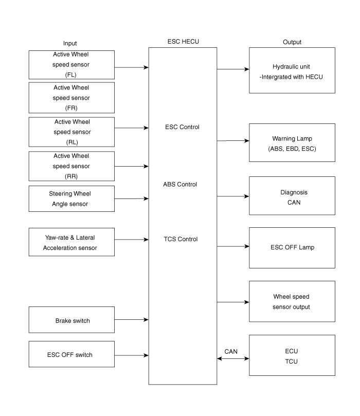
Input and Output Diagram
Cruise Control Operating Mode
ESC / ESCi
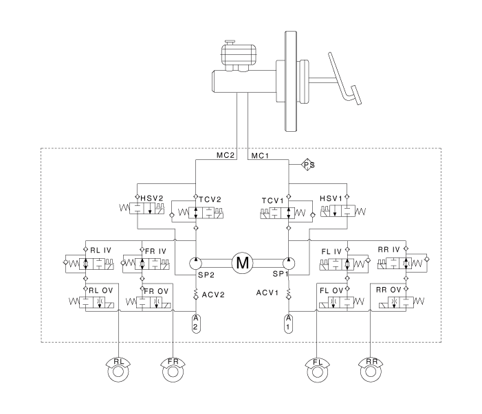
ESC+
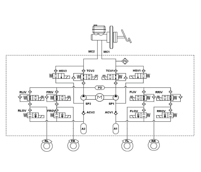
ESC not operating: Normal braking.
Solenoid valve Continuity Valve Motor Pump TC Valve IN (NO) OFF OPEN OFF OFF OUT (NC) OFF CLOSE Cruise Control Operation
Solenoid valve Continuity Valve Motor Pump TC Valve Understeer
(Inside Rear Wheel Only)IN (NO) OFF OPEN ON ON OUT (NC) OFF CLOSE Oversteer
(Outside Front Wheel Only)IN (NO) OFF OPEN OUT (NC) OFF CLOSE
Warning Lamp Control
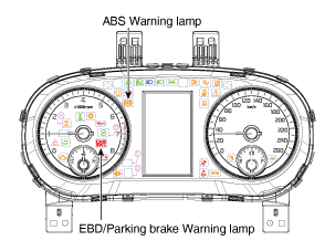
ABS Warning Lamp Module
The active ABS warning lamp module indicates the self-check and malfunction status of the ABS. The ABS warning lamp illuminates under the following conditions:
During the initialization phase after IGN ON (continuously for 3 seconds).
In case of ABS function failure.
In diagnostic mode.
In case of communication failure between HECU and PCM.
The cluster lamp illuminates when communication with the CAN module is not possible.
EBD/Parking Brake Warning Lamp Module
The active EBD warning lamp module indicates the self-check and malfunction status of the EBD. However, if the parking brake switch is on, the EBD warning lamp is always illuminated regardless of EBD operation. The EBD warning lamp illuminates under the following conditions:
During the initialization phase after IGN ON (continuously for 3 seconds).
When the parking brake switch is on or the brake fluid level is low.
When the EBD function has failed.
In diagnostic mode.
In case of communication failure between HECU and PCM.
The cluster lamp illuminates when communication with the CAN module is not possible.
ESC Function / Warning Lamp
The ESC function/warning lamp indicates the self-check and malfunction status of the ESC system.
The ESC function/warning lamp illuminates under the following conditions:
During the initialization phase after IGN ON (continuously for 3 seconds).
When the ESC function is inhibited due to a system failure.
When ESC control is operating. (Flashing - 2 Hz)
In diagnostic mode (other than standard mode).
The cluster lamp illuminates when communication with the CAN module is not possible.
ESC OFF Indicator Lamp
The ESC OFF indicator lamp indicates the self-check and operating status of the ESC.
The ESC OFF indicator lamp operates under the following conditions:
In initialization mode after IGN ON (continuously for 3 seconds).
The ESC OFF lamp illuminates when the driver turns off the ESC switch.
ESC ON/OFF Switch
The ESC ON/OFF switch is used to switch the ESC function between ON and OFF states based on driver actions.
The ON/OFF switch is a normally open momentary contact switch.
The initial state of the ESC function is ON.
Circuit Diagrams
Wiring Diagram
[EPB Not Applied]
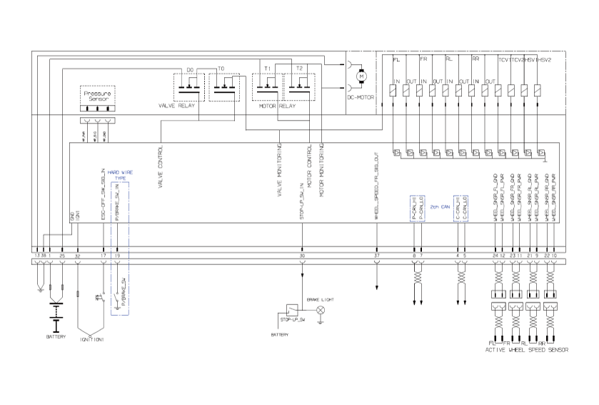
[EPB Applied]
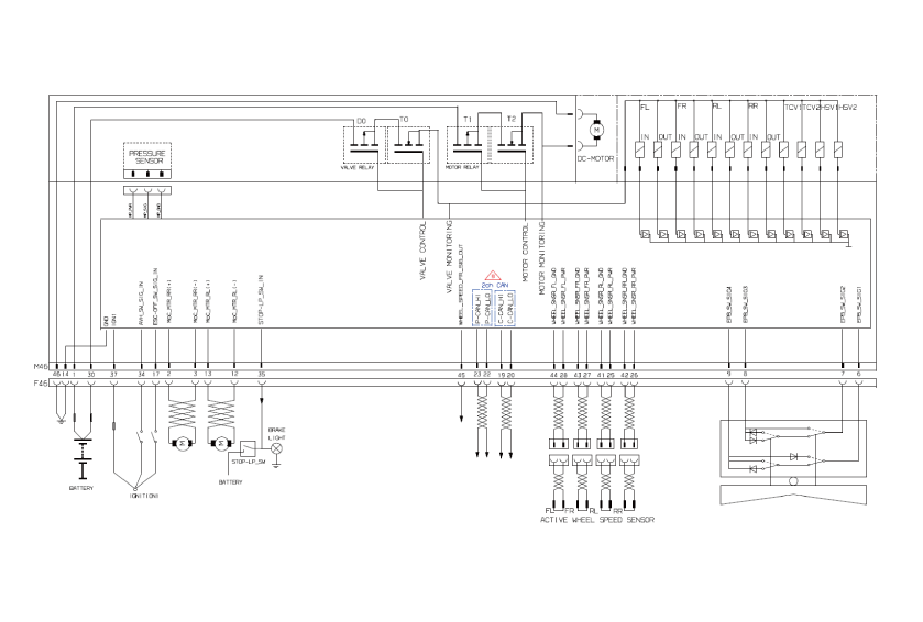
Terminal Function
[EPB Not Applied]
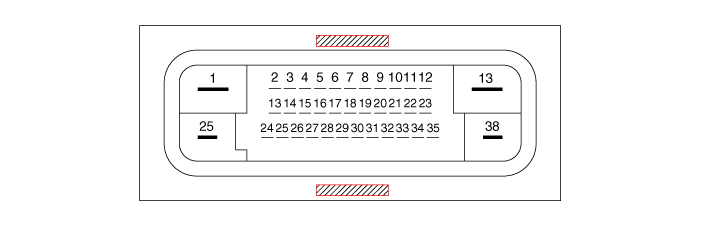
| PIN No. | Description | Current | |
| Max. | min | ||
| 1 | Power Supply for Pump Motor | 40A | 10 MΩ |
| 2 | Hazard Warning Switch | 1.2 mA | 250 MΩ |
| 3 | - | ||
| 6 | |||
| 7 | P-CAN LOW | 100 mA | 250 MΩ |
| 8 | P-CAN HIGH | 100 mA | 250 MΩ |
| 9 | Wheel Speed Sensor Power Supply (RL) | 100 mA | 250 MΩ |
| 10 | Wheel Speed Sensor Power Supply (RR) | 100 mA | 250 MΩ |
| 11 | Wheel Speed Sensor Power Supply (FR) | 100 mA | 250 MΩ |
| 12 | Wheel Speed Sensor Power Supply (FL) | 100 mA | 250 MΩ |
| 13 | Return Pump Ground | 40A | 10 MΩ |
| 14 | - | ||
| 17 | ESC Switch | 1.2 mA | 250 MΩ |
| 18 | - | ||
| 19 | Parking Brake Switch | 1.2 mA | 250 MΩ |
| 20 | - | ||
| 21 | Wheel Speed Sensor Ground (RL) | 40 mA | 250 MΩ |
| 22 | Wheel Speed Sensor Ground (RR) | 40 mA | 250 MΩ |
| 23 | Wheel Speed Sensor Ground (FR) | 40 mA | 250 MΩ |
| 24 | Wheel Speed Sensor Ground (FL) | 40 mA | 250 MΩ |
| 25 | Power Supply for Solenoid Valves | 30A | 10 MΩ |
| 26 | - | ||
| 27 | - | ||
| 28 | - | ||
| 29 | - | ||
| 30 | Stop Lamp Switch | 1.2 mA | 250 MΩ |
| 31 | - | ||
| 32 | IGN 1 | 10 mA | 50 MΩ |
| 33 | - | ||
| 36 | - | ||
| 37 | Wheel Speed Sensor Output (FR) | 50 mA | 250 MΩ |
| 38 | Ground for Solenoid Valves and ECU | 30A | 10 MΩ |
[EPB Applied]
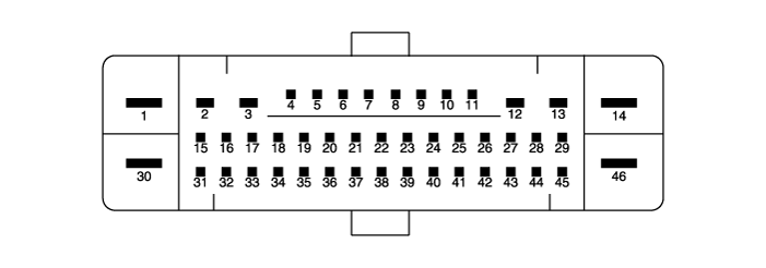
| PIN No. | Description | Current | |
| Max. | min | ||
| 1 | Power Supply for Pump Motor | 39A | 10 MΩ |
| 2 | RR EPB Motor Power | 30A | 10 MΩ |
| 3 | RR EPB Motor Ground | 30A | 10 MΩ |
| 6 | Electronic Parking Brake Signal 1 | 20 mA | 250 MΩ |
| 7 | Electronic Parking Brake Signal 2 | 20 mA | 250 MΩ |
| 8 | Electronic Parking Brake Signal 3 | 20 mA | 250 MΩ |
| 9 | Electronic Parking Brake Signal 4 | 20 mA | 250 MΩ |
| 10 | - | - | 250 MΩ |
| 11 | - | - | - |
| 12 | RL EPB Motor Ground | 30A | - |
| 13 | RL EPB Motor Power | 30A | 10 MΩ |
| 14 | Ground for Solenoid Valves and ECU | 30A | 10 MΩ |
| 16 | - | - | 250 MΩ |
| 17 | ESP OFF Switch Signal | 16.8 mA | |
| 19 | Local CAN High | 10 mA | 250 MΩ |
| 20 | Local Low CAN | 30 mA | 250 MΩ |
| 21 | - | - | 250 MΩ |
| 22 | P-CAN LOW | - | |
| 23 | P-CAN HIGH | 200 mA | 250 MΩ |
| 24 | - | - | 250 MΩ |
| 25 | Wheel Speed Sensor Power Supply (RL) | 16.8 mA | |
| 26 | Wheel Speed Sensor Power Supply (RR) | 16.8 mA | 250 MΩ |
| 27 | Wheel Speed Sensor Power Supply (FR) | 16.8 mA | 250 MΩ |
| 28 | Wheel Speed Sensor Power Supply (FL) | - | 250 MΩ |
| 29 | - | 16.8 mA | 250 MΩ |
| 30 | Power Supply for Solenoid Valves | 30A | |
| 31 | - | - | 10 MΩ |
| 32 | - | Open Drain | |
| 33 | - | - | |
| 34 | Auto Hold ON/OFF Signal | 10 mA | |
| 35 | Stop Lamp Switch | 10 mA | 250 MΩ |
| 37 | IGN 1 | 5A | 250 MΩ |
| 39 | - | 16.8 mA | 250 MΩ |
| 40 | - | - | |
| 41 | - | - | |
| 42 | - | - | 250 MΩ |
| 43 | - | - | 250 MΩ |
| 44 | Wheel Speed Sensor Ground (FL) | 30 mA | 250 MΩ |
| 45 | Wheel Speed Sensor Ground (FR) | 30 mA | 250 MΩ |
| 46 | Return Pump Ground | 40A | 250 MΩ |
Troubleshooting
Troubleshooting
Fault Diagnosis
In principle, ESC and TCS control is prohibited when the ABS has failed.
When an ESC or TCS failure occurs, only the failed system control is prohibited.
The solenoid valve relay must be turned off in case of ESC failure; refer to ABS fail-safe.
The ABS fail-safe information is identical to the fail-safe for systems where ESC is not installed.
Diagnostic Trouble Code Memory
It stores the code as long as backup lamp power is connected. (O)
It stores the code as long as HCU power is on. (X)
Malfunction Check
The initial check is performed immediately after the HECU is powered on.
The valve relay check is performed immediately after IG2 is turned on.
The check is performed continuously while IG2 is on.
The initial check is performed in the following cases.
When a malfunction is detected momentarily
When ABS and ESC are not being controlled.
If the initial check has not been performed after power is supplied to the ECU.
If the vehicle speed exceeds 8 km/h with the stop lamp switch OFF.
When the vehicle speed exceeds 24.8 mph (40 km/h).
The check continues even if the stop lamp is illuminated.
If ABS or ESC control is activated before the initial check, stop the initial check and wait for the HECU power to be supplied again.
The judgment fails in the following cases.
When the power supply is normal.
From the point at which the vehicle speed reaches 8 km/h after the HECU is turned on.
Fail-Safe Measures
Turn the system off, perform the following procedure, and wait until the HECU power is turned OFF.
Turn off the valve relay.
Stop the control during operation and do not perform any action until it returns to normal condition.
Warning Lamp ON
The ESC warning lamps illuminate for 3 seconds after the ignition is turned on.
The ESC function lamp flashes when ESC is active.
In case of an ESC malfunction, the ESC warning lamp illuminates.
The ESC OFF lamp illuminates:
– When ESC is turned off
– 3 seconds after IGNITION ON
Test yourself
A quick Kia Optima DL3 quiz: every answer comes with an explanation and a link to the manual page.