Power Window Switch
Circuit Diagrams
Connector and Terminal Function
Power window main switch
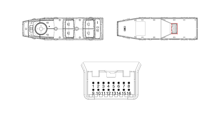
| Pin | Function |
| 1 | B-CAN (Low) |
| 2 | B-CAN (High) |
| 3 | Ground (Security Assist) |
| 4 | Security Assist |
| 5 | LIN (for IMS) |
| 6 | Battery (+) |
| 7 | IGN1 |
| 8 | Driver Safety |
| 9 | IMS Switch (for IMS) / Mirror Switch (for non-IMS) |
| 10 | Mirror Unfolding Motor (non-IMS) |
| 11 | Mirror Folding Motor (non-IMS) |
| 12 | Mirror Horizontal LH (non-IMS) |
| 13 | Mirror Vertical LH (non-IMS) |
| 14 | Mirror Vertical RH (non-IMS) |
| 15 | Mirror Horizontal RH (non-IMS) |
| 16 | Ground |
Auxiliary Power Window Switches
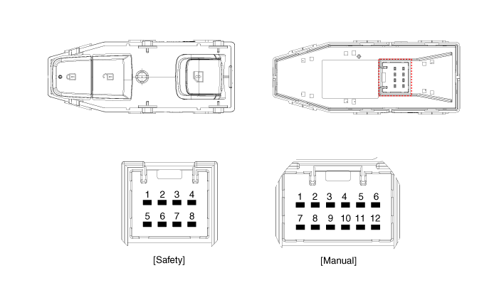
| Pin | Function | |
| Security Type | Manual Type | |
| 1 | Ground (Lighting -) | Ground |
| 2 | Door Lock Switch | Door Lock Switch |
| 3 | Door Unlock Switch | Window Down Motor |
| 4 | Battery + (Illumination +) | Door Unlock Switch |
| 5 | Ground | Window up motor |
| 6 | Door lock indicator | Door lock indicator |
| 7 | Power Window Safety | Driver window down |
| 8 | - | Power window enable |
| 9 | Ground (Lighting -) | |
| 10 | Driver window up | |
| 11 | Ground (Illumination +) | |
| 12 | Battery (+) | |
Rear power window switch
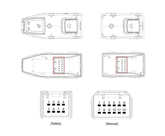
[Seat Heater Type]
| Pin | Function | |
| Security Type | Manual Type | |
| 1 | Ground (Lighting -) | Ground |
| 2 | Seat heater (high) | Seat heater (high) |
| 3 | Seat heater (low) | Window Down Motor |
| 4 | Battery + (Illumination +) | Seat heater (low) |
| 5 | Ground | Window up motor |
| 6 | - | Seat heater switch |
| 7 | Power Window Safety | Driver window down |
| 8 | Seat heater switch | Power window enable |
| 9 | Ground (Lighting -) | |
| 10 | Driver window up | |
| 11 | Battery + (Illumination +) | |
| 12 | Battery (+) | |
[Non-Seat Heater Type]
| Pin | Function | |
| Security Type | Manual Type | |
| 1 | Ground (Lighting -) | Ground |
| 2 | - | - |
| 3 | - | Window Down Motor |
| 4 | Battery + (Illumination +) | - |
| 5 | Ground | Window up motor |
| 6 | - | - |
| 7 | Power Window Safety | Driver window down |
| 8 | - | Power window enable |
| 9 | Ground (Lighting -) | |
| 10 | Driver window up | |
| 11 | Battery + (Illumination +) | |
| 12 | Battery (+) | |
Repair Procedures
Inspection
Diagnosis using KDS
In the body electrical system, faults can be quickly diagnosed using the Korean Diagnostic System (KDS).
The Diagnostic System (KDS) provides the following information.
Self-Diagnosis: Checks malfunction and Diagnostic Trouble Code (DTC)
Current Data: Check the system input/output status.
Actuation Test: Check the system operating status
Additional function: Control of other functions, including the setting parameter system and zero point adjustment.
Select "Vehicle Model" and "DDM" for inspection to check the vehicle with the scan tool.
Select the "Current Data" menu to view the current input/output data status.
To forcibly activate the input value of the module under test, select the "Activation Test" option.
Removal
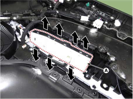
Power window main switch
Disconnect the negative battery cable.
Remove the driver side front door trim panel.
(Refer to Body - "Front Door Trim Panel")
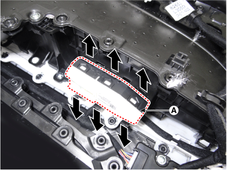
Remove the power window master switch (A) by pressing the retainers in the direction of the arrow.
Auxiliary Power Window Switches
Disconnect the negative battery cable.
Remove the front passenger door trim panel.
(Refer to Body - "Front Door Trim Panel")
Remove the power window auxiliary switch (A) by pressing the retainers in the direction of the arrow.
Rear power window switch
Disconnect the negative battery cable.
Remove the rear door trim.
(Refer to Body - "Rear Door Trim Panel")
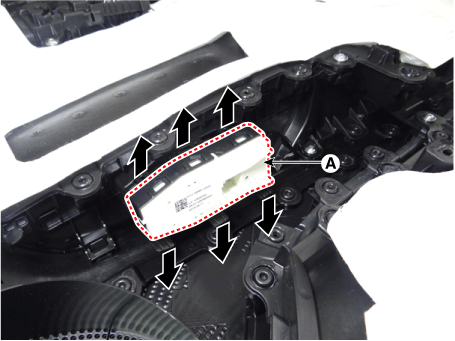
Remove the rear power window switch (A) by pressing the retainers in the direction of the arrow.
Installation
Install in the reverse order of removal.
Test yourself
A quick Kia Optima DL3 quiz: every answer comes with an explanation and a link to the manual page.