Rear Wheel Speed Sensor
Components and Component Location
Components
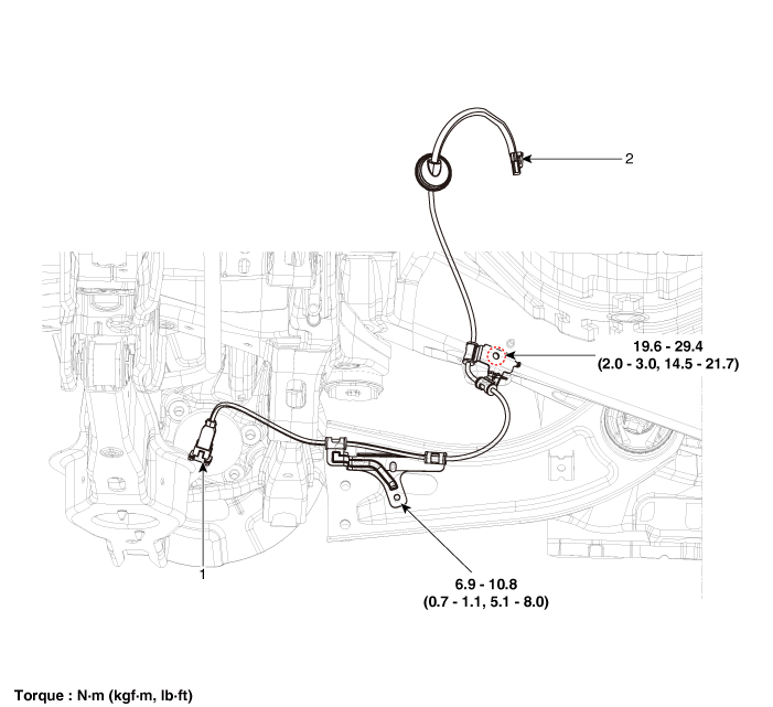
| 1. Rear Wheel Speed Sensor |
2. Rear wheel speed sensor connector |
Repair Procedures
Removal
Disconnect the negative (-) battery cable.
Remove the rear wheel and tire.
(See Suspension System — Wheel)
Remove the rear brake disc.
(Refer to Brake System - "Rear Brake Disc")
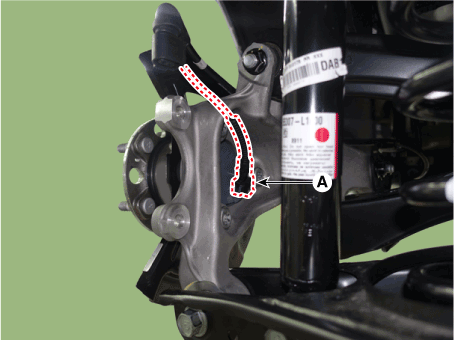
Disconnect the rear wheel speed sensor connector (A).
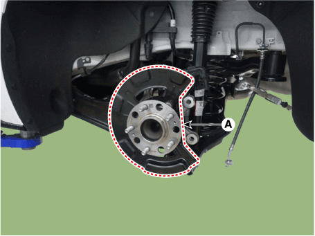
Remove the hub assembly and dust cover (A) after loosening the mounting bolts.
Tightening torque: 88.3–108 N·m
Replacement
Rear Wheel Speed Sensor Cap
Remove the rear wheel hub bearing assembly.
(Refer to Drive Shaft and Axle - "Rear Axle Assembly")
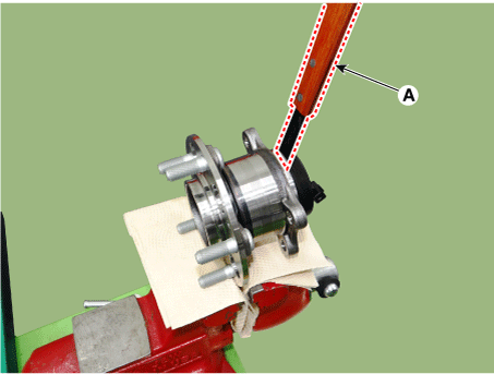
Secure the rear wheel hub bearing assembly (A) in a vise.
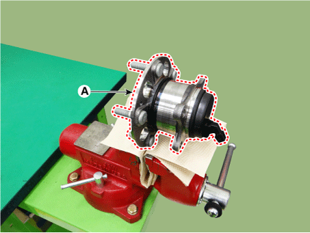
Check the direction of the sensor cover (A).
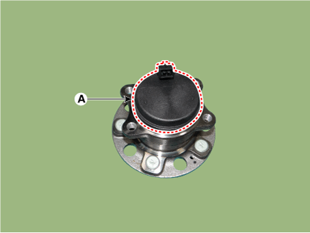
Remove the sensor cover by tapping the gap between the sensor cover and the hub bearing assembly with a scraper (A).
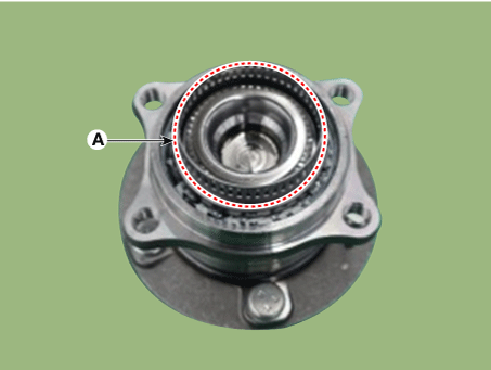
Check the tone wheel or encoder (A) for distortion or damage.
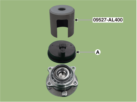
Position the sensor cover in the same direction as the sensor cover connector (A) was positioned before removal.
Install the sensor cover (A) using the Special Service Tool (09527-AL400).
Install the rear wheel hub bearing assembly.
(Refer to Drive Shaft and Axle - "Rear Axle Assembly")
Inspection
Measure the output voltage between the wheel speed sensor terminal and body ground.
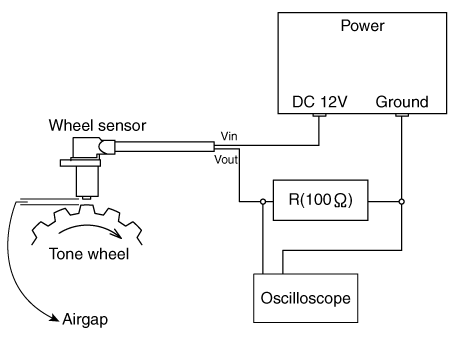
Compare the change in the wheel speed sensor output voltage with the normal output voltage change, as shown below.
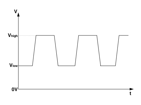
V_low: 0.59–0.84 V
V_high: 1.18–1.68 V
Frequency range: 1–2,500 Hz
Installation
Install in the reverse order of removal.
Test yourself
A quick Kia Optima DL3 quiz: every answer comes with an explanation and a link to the manual page.