Relaxion Comfort Seat
Components and Component Location
Component Location
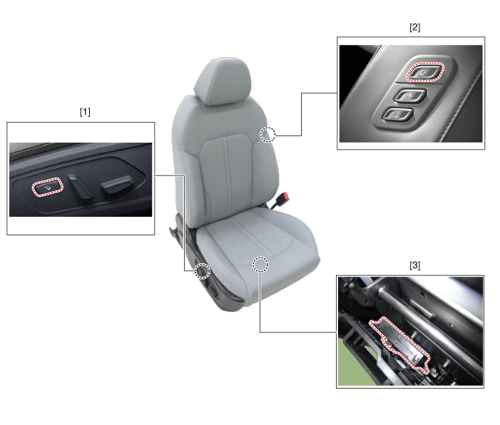
| 1. Relaxion Mode Switch 2. Walk-in Idle Switch |
3. Relaxion Comfort Seat (RCS) |
Circuit Diagrams
Connector and Terminal Function
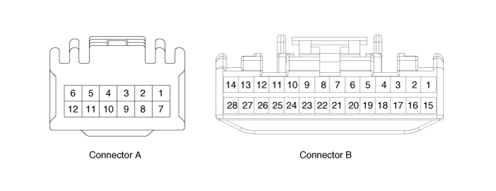
| Pin | Function | |
| Connector A | Connector B | |
| 1 | Battery (+) | Slide Motor Switch (Forward) |
| 2 | Slide Motor (Forward) | Slide Motor Switch (Backward) |
| 3 | Slide Motor (Backward) | Relaxion Comfort Switch (Forward) |
| 4 | Tilt Motor (Forward) | Relaxion Comfort Switch (Backward) |
| 5 | Tilt Motor (Backward) | Rear Height Motor Switch (Up) |
| 6 | Ground | Rear Height Motor Switch (Down) |
| 7 | Battery (+) | Relaxion Comfort Switch |
| 8 | - | Return Switch |
| 9 | Rear Height Motor (Up) | - |
| 10 | Rear Height Motor (Down) | - |
| 11 | - | Sensor Power |
| 12 | Ground | IGN2 |
| 13 | IGN1 | |
| 14 | ECU (Battery +) | |
| 15 | Walk-In Slide Switch (Forward) | |
| 16 | Walk-In Slide Switch (Backward) | |
| 17 | Walk-In Recline Switch (Forward) | |
| 18 | Walk-In Recline Switch (Backward) | |
| 19 | Relaxion Comfort Switch | |
| 20 | Return Switch | |
| 21 | ECU (ground) | |
| 22 | - | |
| 23 | - | |
| 24 | Maximum Set Power | |
| 25 | Slide Motor Sensor | |
| 26 | Tilt Motor Sensor | |
| 27 | Rear Height Motor Sensor | |
| 28 | Virtual Limit Switch | |
Repair Procedures
Removal
Walk-in Switch
Remove the switch.
(Refer to Power Seat Electrical System - "Walk-in Switch")
Relaxion Comfort Switch
Remove the relaxion comfort switch.
(Refer to Power Seat Electrical System - "Power Seat Control Switch")
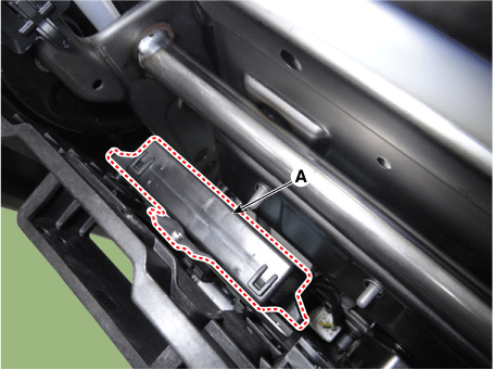
Relaxion Comfort Seat Unit (RCS)
Disconnect the negative battery cable.
Remove the front passenger seat assembly.
(Refer to Body - "Front Seat Assembly")
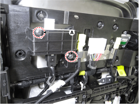
Loosen the mounting screws of the occupant detection sensor (A).
Remove the occupant detection sensor (B) by disconnecting the connector (A).
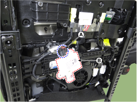
Disconnect the side airbag connector (B) by releasing the lock clip (A).
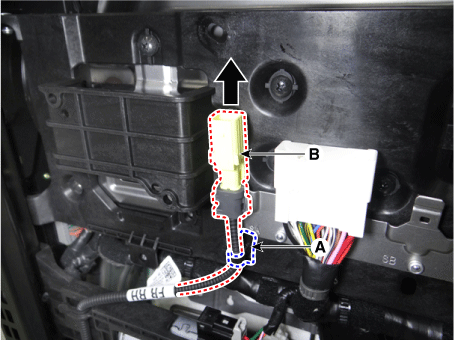
Remove the retaining clips of the RCS unit (A).
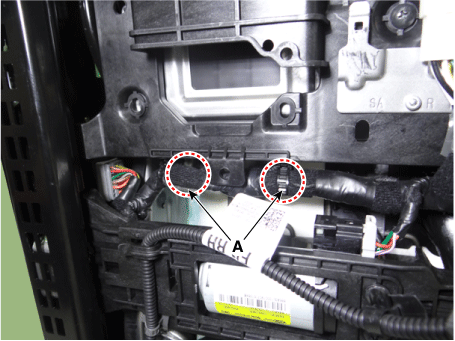
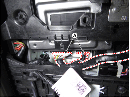
Disconnect the connectors of the RCS unit (A).
Loosen the mounting screws of the RCS unit (A).
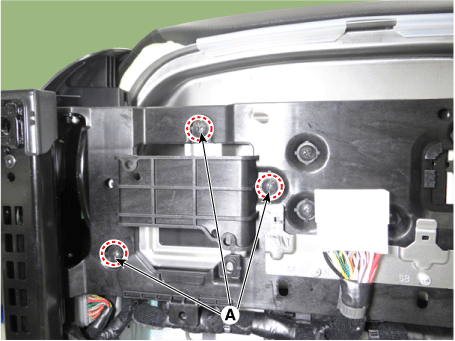
Remove the RCS unit (A).
Installation
Install in the reverse order of removal.
Test yourself
A quick Kia Optima DL3 quiz: every answer comes with an explanation and a link to the manual page.