Seat ventilation and heater switch
Circuit Diagrams
Connector and Terminal Function
[Front Seat]
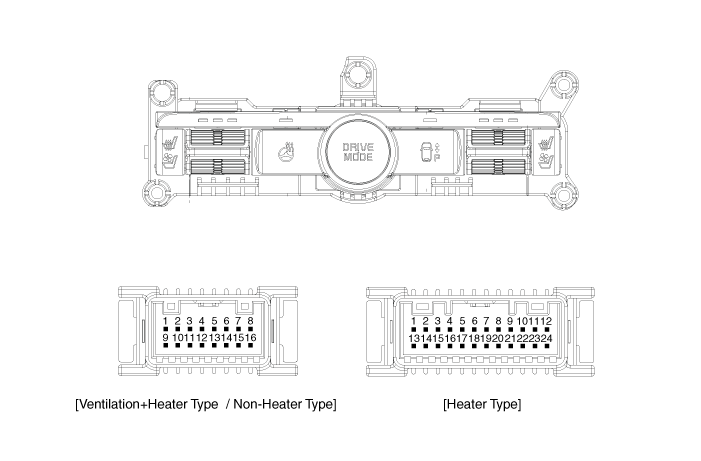
[Ventilation+Heater Type / Type Without Heater]
| Pin | Function | Pin | Function | ||
| Ventilation + Heater Type | Type without Heater | Ventilation + Heater Type | Type without Heater | ||
| 1 | IGN1 | - | 9 | Illumination (+) | |
| 2 | - | - | 10 | - | |
| 3 | - | - | 11 | Illumination (-) | |
| 4 | Ground | - | 12 | - | |
| 5 | - | 13 | Steering Wheel Heater Mode | - | |
| 6 | - | 14 | Steering Wheel Heater Indicator | - | |
| 7 | LIN | - | 15 | Driver Mode Switch (CW) | |
| 8 | Ground | 16 | Driver Mode Switch (CCW) | ||
[Heater Type]
| Pin | Function | Pin | Function |
| 1 | Heater indicator (high)_RH | 13 | Heater Mode_RH |
| 2 | Heater Indicator (Middle)_RH | 14 | - |
| 3 | Heater indicator (low)_RH | 15 | - |
| 4 | - | 16 | Ground |
| 5 | Driver Mode Switch (CW) | 17 | - |
| 6 | Driver Mode Switch (CCW) | 18 | Illumination (-) |
| 7 | Steering Wheel Heater Mode | 19 | - |
| 8 | Steering Wheel Heater Indicator | 20 | Illumination (+) |
| 9 | Heater Mode_LH | 21 | - |
| 10 | Heater indicator (high)_LH | 22 | - |
| 11 | Heater Indicator (Middle)_LH | 23 | - |
| 12 | Heater indicator (low)_LH | 24 | - |
[Rear Seat]
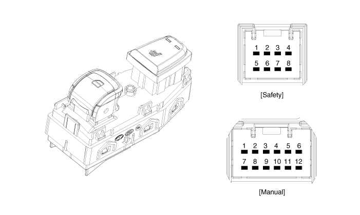
[Security Type]
| Pin | Function | Pin | Function |
| 1 | Ground (Lighting -) | 5 | Ground |
| 2 | Door Lock Switch | 6 | Door lock indicator |
| 3 | Door Unlock Switch | 7 | Power Window Safety |
| 4 | Battery + (Illumination +) | 8 | - |
[Manual Type]
| Pin | Function | Pin | Function |
| 1 | Ground | 7 | Driver window down |
| 2 | Seat heater (high) | 8 | Power window enable |
| 3 | Window Down Motor | 9 | Ground (Lighting -) |
| 4 | Seat heater (low) | 10 | Driver window up |
| 5 | Window up motor | 11 | Battery + (Illumination +) |
| 6 | Seat heater switch | 12 | Battery (+) |
Repair Procedures
Inspection
[Front Seat]
Disconnect the negative battery cable.
Remove the console upper cover.
(Refer to Body - Floor Console Assembly)
Press and hold the switch, then check the continuity between the signal terminal and the ground terminal.
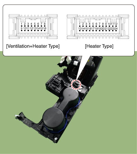
[Heater Switch]
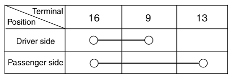
[Rear Seat]
Disconnect the negative battery cable.
Remove the rear door trim.
(Refer to Body - "Rear Door Trim Panel")
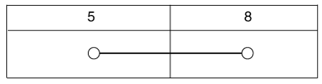
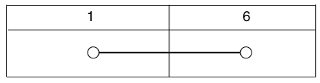
Press and hold the switch, then check the continuity between the signal terminal and the ground terminal.
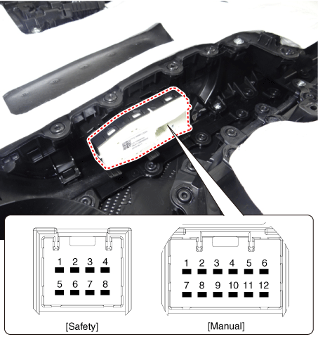
[Safety]
[Manual]
Removal
[Front Seat]
Disconnect the negative battery cable.
Remove the console upper cover.
(Refer to Body - Floor Console Assembly)
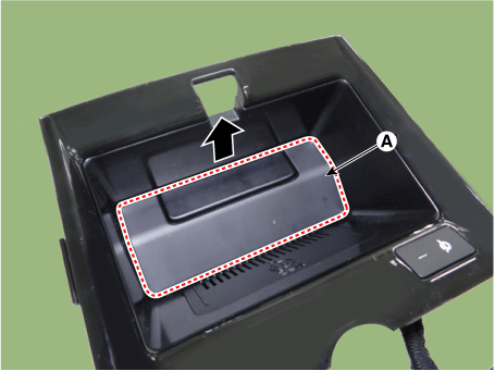
Remove the wireless charging pad (A).
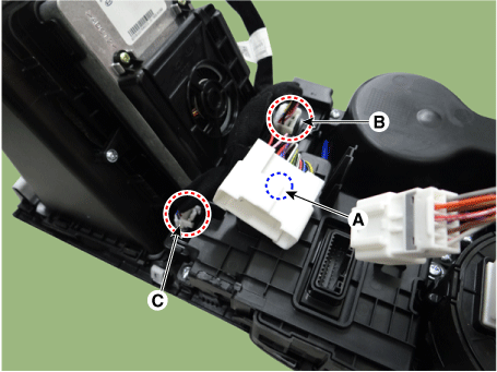
Fully disconnect all connectors from the floor console switch.
(A): Main connector locking clip
(B): Floor console switch full connector
(C): Wireless charging indicator connector
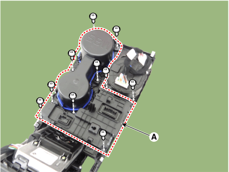
Remove the console cup holder assembly (A) after loosening the mounting screws.
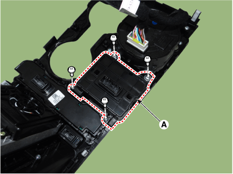
Remove the EPB switch assembly (A) after loosening the mounting screws.
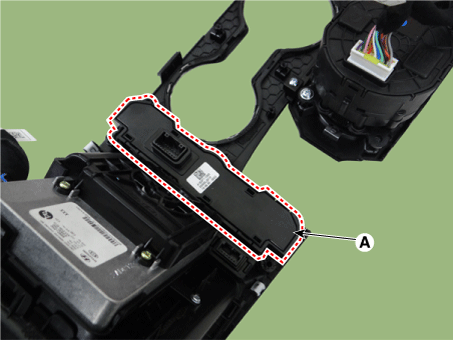
Fully remove the floor console switch (A).
[Rear Seat]
Disconnect the negative battery cable.
Remove the rear power window switch.
(Refer to Power Windows - "Power Window Switch")
Installation
Install in the reverse order of removal.
Test yourself
A quick Kia Optima DL3 quiz: every answer comes with an explanation and a link to the manual page.