Timing Chain Cover
Components and Component Location
Components
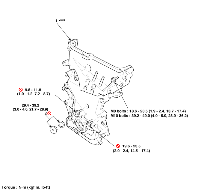
| 1. Timing Chain Cover | 2. Service Plug Bolt and Gasket |
Repair Procedures
Removal
Engine removal is not necessary for this procedure.
Disconnect the negative battery cable.
Remove the right front wheel.
Remove the engine cover.
(See Engine and Transaxle Assembly - Engine Cover)
Remove the engine room cover.
(See Engine and Transaxle Assembly - Under Hood)
Remove the drive belt.
(See Drive Belt System - Drive Belt)
Remove the crankshaft damper pulley.
(See Drive Belt System - "Crankshaft Damper Pulley")
Remove the water pump.
(See Cooling System - "Water Pump")
Remove the drive belt tensioner.
(Refer to Drive Belt System - "Drive Belt Tensioner")
Remove the idler.
(See Drive Belt System - "Idler Pulley")
Remove the generator.
(See Engine Electrical System - "Alternator")
Remove the air conditioning compressor.
(See Heating, Ventilation and Air Conditioning - "Compressor")
Drain the engine oil and remove the oil pan.
(See Lubrication System - "Oil Pan")
Remove the front engine mount (A).
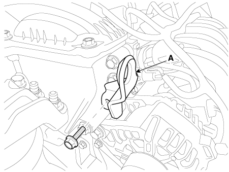
Remove the generator.
(See Engine Electrical System - "Alternator")
Remove the engine mounting bracket.
(See Engine & Transaxle Assembly - "Engine Mounting")
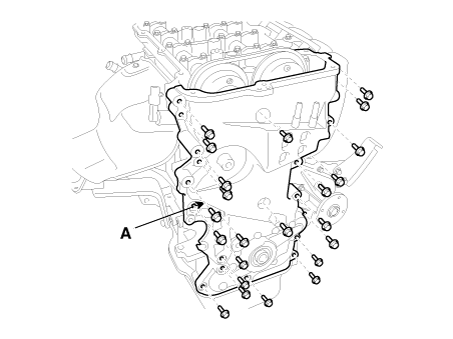
Remove the timing chain cover (A) by carefully prying at the gaps between the cylinder head and cylinder block.
Installation
Install the timing chain cover.
Using a gasket scraper, remove all old gasket material from the sealing surfaces.
The sealant application areas on the timing chain cover and mating parts (cam carrier, cylinder head, cylinder block and oil pan) must be cleaned of foreign material, oil, dust and moisture. Spray the cleaning agent onto the surface and wipe with a clean cloth.
Before installing the timing chain cover, apply liquid sealant to the gap between the cam carrier, cylinder head and cylinder block.
Bead width: 3.0–5.0 mm (0.11–0.20 in.)
Sealant: Threebond 1217H or equivalent.
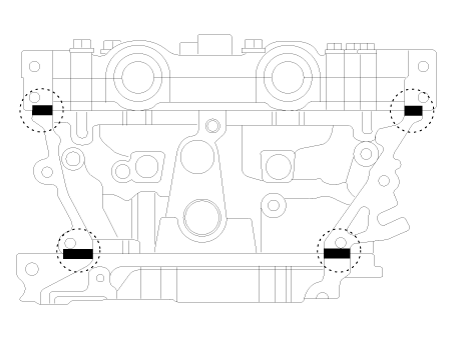
After applying liquid sealant to the timing chain cover, install it within 5 minutes of applying the sealant. A continuous bead of sealant must be applied to prevent any oil leakage.
Side Panel Width
Entire section: 2.5–3.5 mm (0.10–0.14 in.)
Section A: 4.5–5.5 mm (0.18–0.22 in.)
Section B: 8.0–9.0 mm (0.32–0.35 in.)
Sealant: Threebond 1217H or equivalent.
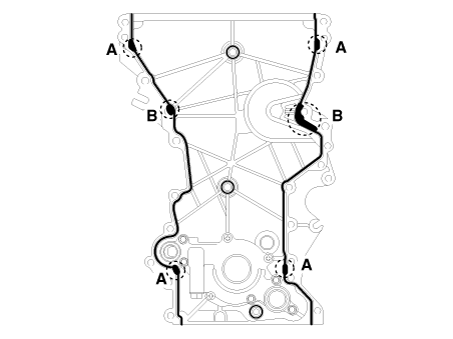
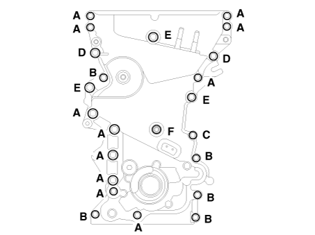
Install the timing chain cover. Use the locating pins on the cylinder block and the holes in the timing chain cover as guides to position the timing chain cover accurately.
Tightening Torque
Bolts (A, B):
18.6–23.5 N·m (1.9–2.4 kgf·m, 13.7–17.4 lbf·ft)
Bolt (C):
19.6–23.5 N·m (2.0–2.4 kgf·m, 14.5–17.4 lbf·ft)
Bolts (D, E):
39.2–49.0 N·m (4.0–5.0 kgf·m, 28.9–36.2 lbf·ft)
Bolt (F):
9.8–11.8 N·m (1.0–1.2 kgf·m, 7.2–8.7 lbf·ft)
If necessary, replace the front oil seal.
(Refer to Valve Train - "Front Oil Seal")
Install the front engine mount bracket (A).
Tightening torque: 34.3–39.2 N·m (3.5–4.0 kgf·m, 25.3–28.9 lbf·ft)
Install the remaining parts in the reverse order of removal.
Add all necessary fluids and check for leaks. Connect the GDS. Check for DTCs, notes, and clean up. Recheck.
Test yourself
A quick Kia Optima DL3 quiz: every answer comes with an explanation and a link to the manual page.