Tightening torques
 Also refer to the various 'exploded views of parts' in the procedures.
AUXILIARY DRIVE
Tensioner pulley bolt: 6.7.
Idler pulley bolt: 2.5.
Auxiliary belt tensioner bracket: 2.
Crankshaft pulley:
1st stage: 20.
2nd stage: 90°.
TIMING
Timing chain drive sprocket bolt: 1.8.
Timing cover bolt: 1.
Chain tensioner: 8.
CYLINDER HEAD
Camshaft bearing cap on cylinder head: 1.2.
Cylinder head cover on cylinder head (*): 1.2.
Front cover (with vacuum pump): 1.2.
Rear cover:
M6 bolt: 1.2.
M8 bolt: 2.6.
Cylinder head bolts on cylinder block (Fig.69):
M8 bolt: 2.
M12 bolt:
1st stage: 1.
2nd stage: 8.
3rd stage: 90°.
4th stage: 90°.
Exhaust manifold to cylinder head: 3
CYLINDER BLOCK
Connecting rod cap to connecting rod:
1st stage: 0.5.
2nd stage: 2.5.
3rd stage: 90°.
Crankshaft main bearing cap:
1st stage: 5.5.
2nd stage: 90°.
Flywheel bolt to crankshaft (manual gearbox):
1st stage: 4.5.
2nd stage: 90°.
Drive plate bolt to crankshaft (automatic gearbox):
1st stage: 4.5.
2nd stage: 90°.
Rear sealing cover to crankcase: 0.9.
Coolant drain plug on cylinder block: 3.
COOLING Coolant drain bolt on cylinder block: 3.
Thermostat housing: 1.4.
Water pump (*): 1.2.
Water pump pulley: 1.3.
LUBRICATION
Oil sump (Fig.33):
1st stage: 0.6.
2nd stage: 1.3.
Oil baffle plate on cylinder block: 1.2.
Braided hose on oil sump: 2.
Engine oil drain plug: 3.
Oil pump on cylinder block: 1.4.
Cover on oil pump: 1.2.
Suction pipe on oil pump: 1.1.
Oil filter housing: 1.2.
Oil filter cover: 2.5.
Oil cooler on cylinder block: 0.9.
Oil cooler pipe: 0.8.
Oil level, temperature and quality sensor: 0.5.
Banjo bolt, turbo oil supply pipe: 1.5.
Turbo oil return pipe bolt: 0.8.
FUEL SUPPLY
Engine control unit: 0.5.
Temperature sensor on exhaust manifold (particulate filter): 4.5.
Oxygen sensor on catalytic converter: 5.
Banjo bolt, fuel return pipe on rail: 2.
Injector clamp (*):
1st stage: 0.7.
2nd stage: 90°.
3rd stage: 90°.
High-pressure pump on cylinder head: 1.4.
High-pressure pipe, pump to rail:
14 mm nut: 2.2 daN.m.
18 mm nut: 2.7 daN.m.
High-pressure pipe, rail to injector:
14 mm nut: 2.2 daN.m.
18 mm nut: 2.7 daN.m.
Banjo bolt on high-pressure pump: 2.
High-pressure rail on cylinder head: 1.6.
Injector cover plate: 1.4.
Fuel high-pressure sensor on common rail: 7.
EGR valve: 1.2.
AIR INTAKE / EXHAUST
Intake air throttle (without particulate filter): 1.2.
Throttle actuator (with particulate filter): 1.2.
EGR valve actuator (with particulate filter): 1.2.
Air filter housing bracket: 1.2.
Exhaust manifold to cylinder head: 3.
Turbocharger bracket: 3.
Heat shield: 1.4.
Water/EGR heat exchanger on cylinder block: 0.8.
(*) Screws or nuts to be replaced after each removal.
Wiring diagrams
KEY
 See explanations and how to read a diagram in the 'Electrical equipment' chapter.
ABBREVIATIONS
ARF. Exhaust gas recirculation.
DPF. Diesel particulate filter.
KAT. Catalytic converter.
KLA. Automatic air conditioning.
ME. Petrol injection and ignition system ME (engine electronics).
O2. Oxygen.
SAM. Signal input and control module.
COMPONENTS
A1. Instrument cluster.
A9. Air conditioning compressor
B2/5. Hot-film mass air flow sensor.
B4/6. Rail pressure sensor.
B5/1. Boost pressure sensor.
B6/1. Camshaft Hall sensor.
B11/4. Coolant temperature sensor.
B17/8. Charge air temperature sensor.
B19/8. Temperature sensor after catalytic converter
B19/9. Temperature sensor before diesel particulate filter
B19/11. Temperature sensor before turbocharger
B28/8. Differential pressure sensor (DPF).
B37. Accelerator pedal sensor.
B40. Oil sensor (oil level, temperature and quality).
B50. Fuel temperature sensor.
B60. Exhaust back pressure sensor.
F55/1. Fuse box 1, 9 times.
F55/1f7. Fuse 7.
F55/2. Fuse box 2, 9 times.
F55/3. Fuse box 3, 9 times.
F55/3f21. Fuse 21.
F55/4. Fuse box 4, 9 times.
F55/5. Fuse box 5, 9 times.
F55/5f43. Fuse 43.
F55/5f44. Fuse 44.
F55/5f45. Fuse 45.
F55/6. Fuse box 6, 9 times.
F55/7. Fuse box 7, 9 times.
F55/9. Fuse box 9.
F55/9f64. Fuse 64.
F55/9f68. Fuse 68.
F55/2f11. Fuse 11.
G1. Battery.
G2. Alternator.
G3/2. Front O2 sensor, before catalytic converter.
G3/2x1. Connector, front O2 sensor before catalytic converter
K100. Fuse and relay box.
K100kK. Fuel pump relay.
K100kL. Engine terminal 87 relay.
K100kM. Starter relay.
L5. Crankshaft position sensor.
M1. Starter motor.
M3/3. Feed pump with fuel gauge.
M3/3b1. Fuel gauge.
M3/3m1. Feed pump.
M4/7. Engine suction fan and air conditioner with integrated control.
M16/5. Throttle valve actuator.
M55. Intake duct shutoff motor.
N3/9. Engine control unit.
N3/10. ME control unit.
N10. SAM control unit.
N14/3. Glow time output stage.
N22. KLA keypad.
N22/7. Keypad and control unit for KLA comfort.
R9. Glow plugs.
R39/1. Air outlet heating element.
S40/3. Clutch pedal switch.
U12. Valid for left-hand drive.
U13. Valid for right-hand drive.
U24. Valid for manual gearbox.
U29. Valid for outside temperature display.
U673. Valid for KLA comfort.
U857. Valid for standard engine fan.
U858. Valid for optional engine fan.
U871. Valid for version with diesel particulate filter.
U872. Valid for version without diesel particulate filter.
U835. Valid for engine 266.
U836. Valid for engine 640.
W1/1. Body chassis ground.
W1/2. Body ground.
W3/1. Front right wheel housing ground (ignition coil).
W3/2. Front left wheel housing ground.
W7. Right wheel housing luggage compartment ground
W10. Battery ground.
W11. Engine ground (screwed cable).
W43. Bulkhead ground.
X11/4. Diagnostic socket.
X14/4. Terminal 50 connector.
X26/29. Engine/engine compartment wiring harness connector.
X36/2. Fuel pump wiring harness/rear light wiring harness connector.
Y27/9. Exhaust gas recirculation actuator.
Y31/5. Pressure converter, boost pressure control.
Y31/13. Pressure converter, ARF/throttle valve.
X63/4. CAN data bus connector, 2-pin.
Y74. Pressure regulator valve.
Y76. Injectors.
Y76y1. Injector, cylinder 1.
Y76y2. Injector, cylinder 2.
Y76y3. Injector, cylinder 3.
Y76y4. Injector, cylinder 4.
Y94. Flow control valve.
Z6/3. Terminal sleeve, 2nd sensor ground.
Z6/30. Terminal sleeve, ground.
Z6/85. Terminal sleeve, sensor ground 1.
Z7/35. Terminal sleeve, terminal 87 M1e.
Z7/36. Terminal sleeve, terminal 87 M2e.
Z7/43. Terminal sleeve, sensor ground.
Z7/5. Terminal sleeve, 87.
Z9. Terminal sleeve 1 (splice welded into wiring harness).
Z36/22. Terminal sleeve, rear warning element power supply (parking aid).
COLOUR CODES
BK: Black
BN: Brown
BU: Blue
GN: Green
GY: Grey
PK: Pink
RD: Red
TR: Transparent
VT: Violet
WH: White
YE: Yellow
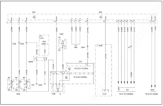
Diesel injection control unit (connector F) (1/2)
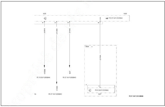
Diesel injection control unit (connector F) (2/2)
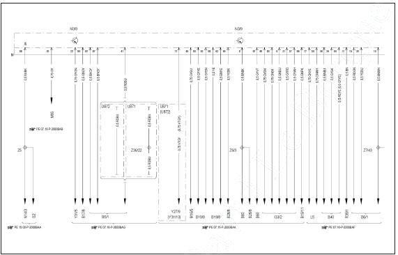
Diesel injection control unit (connector M) (1/2)
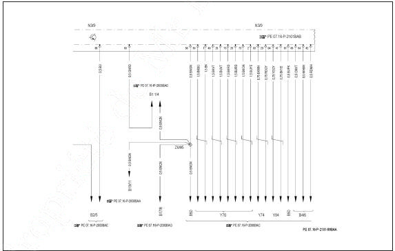
Diesel injection control unit (connector M) (2/2)
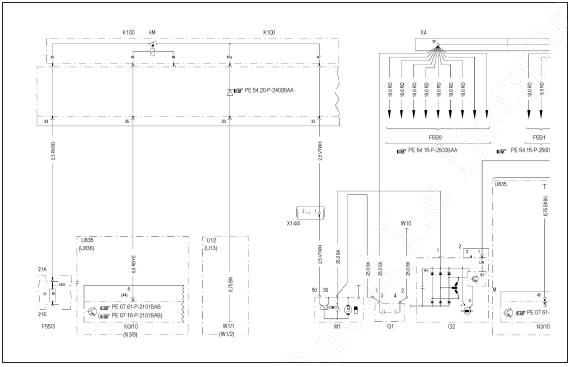
Starter, alternator and glow system (1/2)
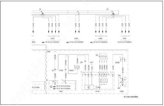
Starter, alternator and glow system (2/2)
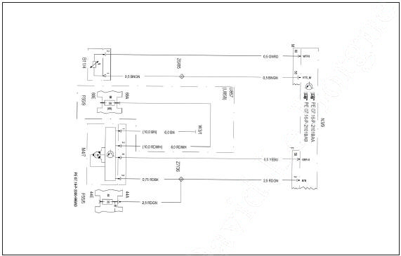
Cooling
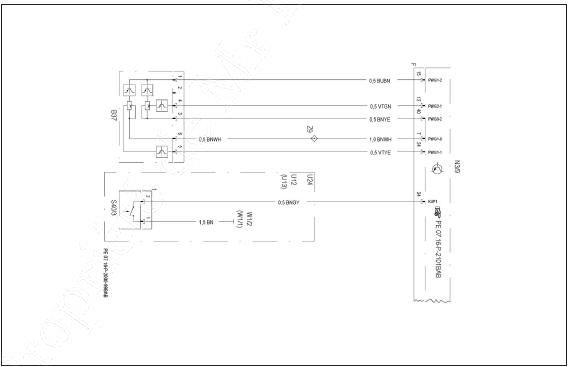
Pedal assembly
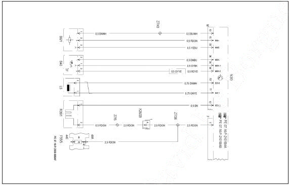
Engine and oil position sensors
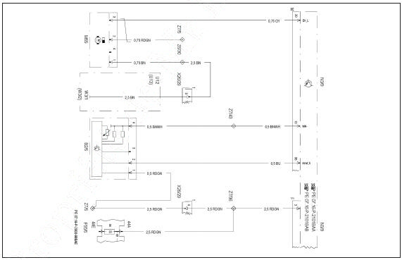
Air intake
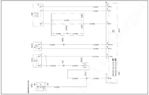
Turbocharging
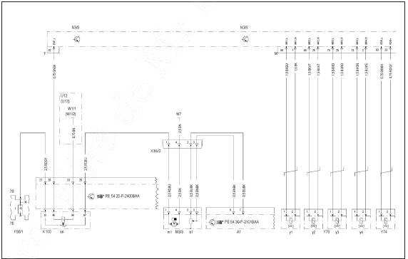
Fuel supply (1/2)
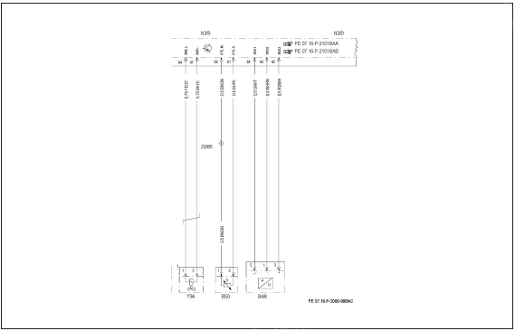
Fuel supply (2/2)
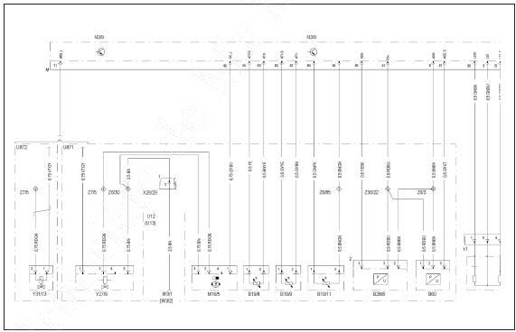
Exhaust system (1/2)
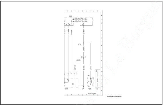
Exhaust system (2/2)
Test yourself
A quick Mercedes-Benz B-Class quiz: every answer comes with an explanation and a link to the manual page.