Diesel engines
Fuel supply - engine management
In this manual: Diesel engines
18steps
~108min
4/5difficulty
Done 0 of 18
PRECAUTIONS TO OBSERVE
Before any work on the low- or high-pressure fuel supply circuits, observe the following instructions:
- Before loosening a high-pressure fitting or removing an injector, clean them with a suitable degreaser. Apply the degreaser with a brush to the line fittings, and to the injectors at their clamp and their seat in the cylinder head. It is recommended to then vacuum the cleaned areas and to avoid using compressed air.
- When loosening the fitting of a high-pressure line, it is advisable to hold the adapter fitting on the component concerned with a second spanner, to prevent it from loosening.
- After disconnecting a line, plug it and the open fitting with suitable caps to prevent contaminants entering the circuit.
- At the end of the work, check the circuit for leaks. To do this, spray a suitable leak detection product on the fittings that were worked on. Let the product dry, then start the engine and check for leaks with the engine running, accelerating it, then carrying out a road test.
If necessary, replace faulty parts.
ENGINE MANAGEMENT ECU
REMOVAL
- Disconnect the battery.
- Without disconnecting its hoses, set the expansion tank aside.
- Disconnect the connectors (1) from the ECU (2) (Fig.45).
- Set the connector (3) aside.
- Remove the ECU by removing the screws (4).
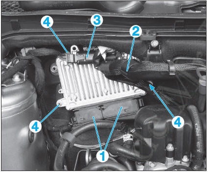
Fig. 45
INSTALLATION
If the ECU has been replaced, the system must be reset using a diagnostic tool.
HIGH-PRESSURE PUMP


REMOVAL
- Remove (Fig.41):
- the air intake pipe (1),
- the air filter housing (2),
- the charge air hose (3).
- Disconnect the connectors of the fuel temperature sensor (4) and of the flow control solenoid valve (5) (Fig.46).
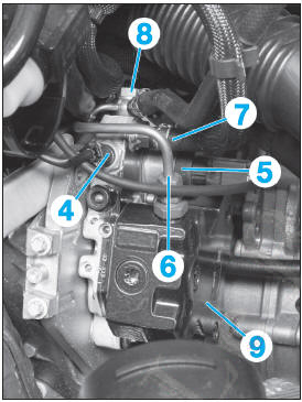
Fig. 46
- Remove:
- the high-pressure line (6),
- the pump supply hose (7),
- the clip (8) of the fuel return pipes.
- Remove the high-pressure pump (9) (3 screws).
 Do not open the high-pressure pump and do not remove the flow control solenoid valve (5).
INSTALLATION
Observe the following points:
- replace the sealing gaskets,
- check the sealing cones on the lines. If punctured, replace the lines,
- only tighten the high-pressure lines to torque once the assembly is in place,
- tighten to the specified tightening torques,
- check for fuel leaks,
- switch the ignition on for 15 seconds so that the high-pressure pump fills with fuel.
HIGH-PRESSURE COMMON RAIL
Before any work on the high-pressure circuit, observe the necessary precautions.REMOVAL
- Disconnect the battery.
- Remove (Fig.41):
- the air intake pipe (1),
- the air filter housing (2).
- Remove the brackets (3) from the air filter housing (Fig.47).
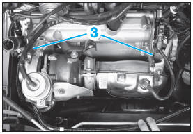
Fig. 47
- Vehicle with particulate filter, remove the exhaust gas recirculation valve actuator (Fig.48):
- remove the coolant hoses from the lines (4),
- disconnect the electrical connector (5),
- remove the screws (6), then the exhaust gas recirculation valve actuator.
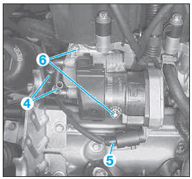
Fig. 48
- Vehicle without particulate filter, remove the exhaust gas recirculation valve actuator (Fig.49):
- remove the hose (4),
- remove the screws (5), then the exhaust gas recirculation valve actuator (6).
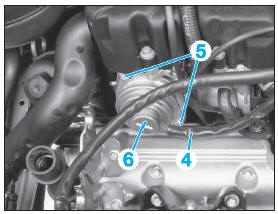 ,.
Fig. 49
- If necessary, disconnect the connector (7) from the pressure sensor (8) on the rail (Fig.50).
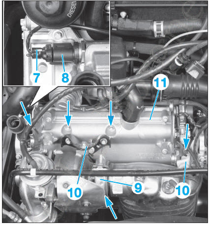
Fig. 50
- Remove:
- the clamp (9),
- the exhaust brackets (10),
- the screws (arrows), then the injector cover plate (11).
- If not already done, disconnect the connector (7) from the pressure sensor (8) on the rail (Fig.51).
- Disconnect the connector from the fuel pressure control solenoid valve (12).
- Cut the cable ties (13).
- Remove the hose (14).
- Remove the lines (15) and (16).
- Remove the injection rail (17) (2 screws).
 Do not remove the fuel pressure control solenoid valve (12) from the injection rail.
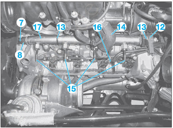
Fig. 51
INSTALLATION
Observe the following points:
- check the sealing cones on the lines. If punctured, replace the lines,
- only tighten the injection rail to torque once the injector lines (15) are fitted without being tightened,
- only tighten the high-pressure lines to torque once the assembly is in place,
- refit the cable ties (13) in the same position as before removal,
- observe the specified tightening torques,
- check the fuel system for leaks.
INJECTORS
REQUIRED TOOLS
- [1]. Extraction claw (ref. 640 589 00 33 00) (Fig.53).
REMOVAL
 Before any work on the high-pressure circuit, observe the necessary precautions.
If several injectors must be removed, mark them so they can be refitted in their original positions.
- Disconnect the battery.
- Remove (Fig.41):
- the air intake pipe (1),
- the air filter housing (2),
- the engine undertray,
- the turbocharger (see relevant operation).
- Remove the brackets (3) from the air filter housing (Fig.47).
- Vehicle with particulate filter, remove the exhaust gas recirculation valve actuator (Fig.48):
- remove the coolant hoses from the lines (4),
- disconnect the electrical connector (5),
- remove the screws (6), then the exhaust gas recirculation valve actuator.
- Vehicle without particulate filter, remove the exhaust gas recirculation valve actuator (Fig.49):
- remove the hose (4),
- remove the screws (5), then the exhaust gas recirculation valve actuator (6).
- If necessary, disconnect the connector (7) from the pressure sensor (8) on the rail (Fig.52).
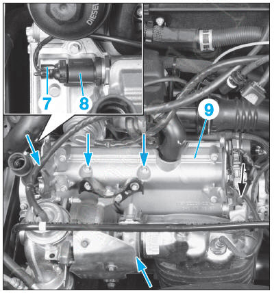
Fig. 52
- Remove the screws (arrows), then the injector cover plate (9).
- Disconnect the connector (10) from the injector (11) (Fig.53).
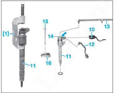
Fig. 53
- Remove the injector line (12).
- Remove the fuel leak-off return line (13) after compressing the clip (14) (arrow).
The clip (14) remains on the injector.- Remove the screw (15) from the injector clamp (16), then remove the clamp.
- Remove the injector.
If the injector is stuck, fit tool [1] in place of the clamp (16) and extract the injector with a slide hammer puller.INSTALLATION
- Refit all previously removed components observing the following points:
- clean the injector and its bore with a brass brush,
- check the sealing cones on the lines. If punctured, replace the lines,
- replace the screw (15),
- only tighten the injector to torque once the injector line (12) is fitted (without tightening) to the rail and the injector,
- if the clip (14) was removed from the injector, replace it with a new one,
- replace the sealing gaskets,
- observe the specified tightening torques,
- check the fuel system for leaks.
If one of the injectors is replaced with a new one, the 'IMA' code must be programmed into the engine management ECU using the diagnostic tool. This code corresponds to corrections that standardise the injected fuel quantities.FUEL FILTER
REMOVAL
- Disconnect the battery.
- Disconnect (Fig.54):
- the fuel supply line (1),
- the fuel outlet line to the pump (2). Open the clips (3) securing the filter.
- Lift the fuel filter out from the top.
INSTALLATION
Observe the following points:
- replace the clamps on lines (1) and (2),
- check the fuel system for leaks.
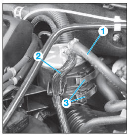
Fig. 54
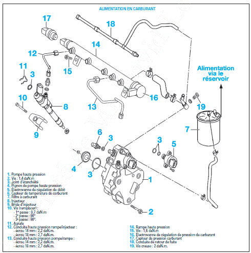
Fuel supply
- High-pressure pump
- Screw: 1.4 daN.m
- Seal
- High-pressure pump gear
- Fuel flow control solenoid valve
- Fuel temperature sensor
- Fuel filter
- Injector
- Injector clamp
- Screw (replace):
- 1st pass: 0.7 daN.m
- 2nd pass: 90°
- 3rd stage: 90°.
- Clip
- High-pressure line rail/injector:
- 14 mm nut: 2.2 daN.m.
- 18 mm nut: 2.7 daN.m.
- High-pressure line pump/rail:
- 14 mm nut: 2.2 daN.m.
- 18 mm nut: 2.7 daN.m.
- High-pressure rail
- Screw: 1.6 daN.m
- Fuel pressure control solenoid valve
- Fuel pressure sensor
- Fuel leak-off return line
- Banjo bolt: 2 daN.m.
Test yourself
A quick Mercedes-Benz B-Class quiz: every answer comes with an explanation and a link to the manual page.
Was this page helpful?