Diesel engines
Cooling system
In this manual: Diesel engines
18steps
~108min
4/5difficulty
Done 0 of 18
REPLACING THE COOLANT
REQUIRED TOOLS
- [1]. Check plug (ref. 169 589 00 91 00) (Fig.36).
DRAINING
 The engine must be cold.
- Disconnect the battery.
- Remove the expansion tank cap.
- Raise and support the front of the vehicle.
- Remove the engine undertray.
- Place a container under the radiator and the cylinder block to collect the coolant.
- Open the radiator drain plug (1) and the cylinder block drain plug (2) (Fig.35).
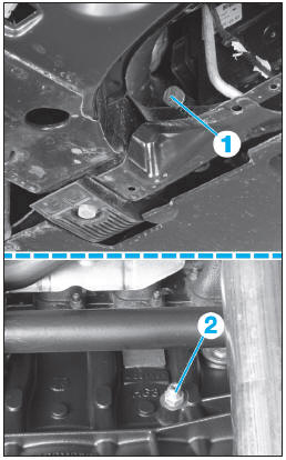
Fig. 35
- Allow the coolant to drain completely.
- Close plugs (1) and (2).
FILLING AND BLEEDING
 Never reuse used coolant when replacing the radiator, the cylinder head or the cylinder head gasket.
- Screw the check plug [1] onto the expansion tank (1) (Fig.36).
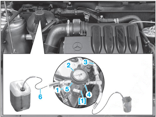
Fig. 36
- Connect the control unit (2) to the check plug [1].
- As illustrated, set up an assembly to create a vacuum to fill and bleed the cooling system.
- Connect a compressed air hose (3).
- Open the outlet valve (4) (a vacuum is created in the cooling system).
- Open the inlet valve (5) long enough for the inlet hose (6) to fill with coolant.
- Close the outlet valve (4) when the display of the control unit (2) is in the green range.
- Remove the compressed air hose (3) and check that the vacuum remains stable for 30 seconds.
- Open the inlet valve (5) (the cooling system fills).
- Open the outlet valve (4) when coolant is no longer being drawn in.
- Remove the assembly.
- Fill the expansion tank up to the base of the filler tube.
WATER PUMP
REQUIRED TOOLS
- [1]. Subframe retaining bolt (ref. 169 589 00 62 00) (Fig.37).
REMOVAL
- Remove the air filter housing.
- Lower the subframe:
- remove the air filter housing,
- the throttle actuator (vehicles with particulate filter) or the intake air throttle (vehicles without particulate filter),
- remove the steering column universal joint bolt, then separate the joint (lock the steering wheel),
- support the radiator,
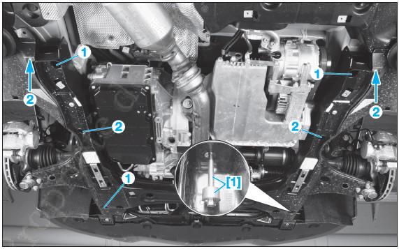
Fig. 37
- remove the engine undertray.
- move the rear of the wheel arch liners aside,
- unhook the rubber exhaust mountings,
- remove the earth strap bolt from the oil sump,
- with manual gearbox, unclip the clutch hydraulic control pipe from the gearbox and the bulkhead,
- with xenon headlamps, disconnect the height sensor connector and remove its mountings,
- fit a support device under the subframe,
- remove the 4 subframe mounting bolts (1) (Fig.37),
- in place of the subframe mounting bolts, fit the retaining bolts with the stops [1],
 Make sure the stops are centred on the retaining bolts.
- remove the 4 subframe mounting bolts (2),
- lower the subframe.
 Before lowering the subframe, make sure no wiring harness, hose or pipe will obstruct its descent.
- Drain the cooling system (see relevant operation).
- Remove the auxiliary drive belt (see relevant operation).
- Remove the bolts (3) from the water pump pulley (4) (fig.38).
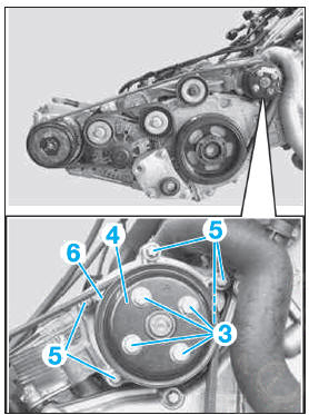
Fig. 38
- Remove the bolts (5), then remove the water pump (6).
INSTALLATION
Observe the following points:
- clean the mating surface on the cylinder block and on the water pump housing,
- replace the sealing gasket,
- refill the cooling system and bleed it.
THERMOSTAT HOUSING
REMOVAL
- Remove the air filter housing.
- Remove (Fig.39):
- vehicles without particulate filter, the intake air throttle,
- vehicles with particulate filter, the motorized throttle body.
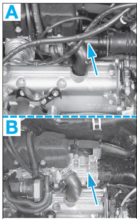
Fig. 39
- Vehicle without particulate filter
- Vehicle with particulate filter.
- Drain the cooling system (see relevant operation).
- Disconnect the various hoses attached to the thermostat housing.
- Remove the screws (1) then the thermostat housing (2) (Fig.40).
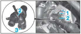
Fig. 40
INSTALLATION
Observe the following points:
- replace the seal (3),
- refill the cooling system and bleed it.
ENGINE COOLING RADIATOR
REMOVAL
- Vehicles up to identification number J176282: drain the air conditioning circuit.
- Remove the engine undertray.
- Drain the cooling system (see relevant operation).
- Remove the front bumper (see the relevant operation in the 'BODYWORK' chapter).
- Remove (Fig.41):
- the air intake pipe (1),
- the air filter housing (2).
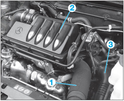
Fig. 41
- Remove (Fig.39):
- vehicles without particulate filter, the intake air throttle,
- vehicles with particulate filter, the electronic throttle body,
- the charge air hose (3) (Fig.41).
- Remove the charge air/air intercooler.
- Without disconnecting its lines, set the windscreen washer reservoir aside.
- Secure the radiator so that it does not fall.
- Vehicles with automatic gearbox: remove the screws (4) of the gearbox lines (Fig.42).
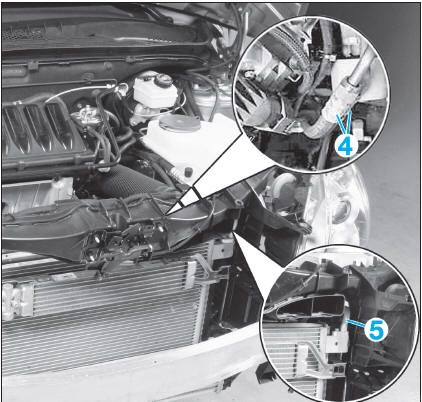
Fig. 42
- Disconnect or unclip the various connectors, cable ties or lines on the fan support.
- Remove the radiator hoses.
- Vehicles up to identification number J176282:
- remove the line (5),
- disconnect the air conditioning pressure switch connector (6) (Fig.43),
- remove the line (7),
- remove the dehydrator (8).
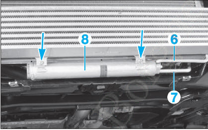
Fig. 43
- Remove the screws (9) then the lower crossmember (10) (Fig.44).
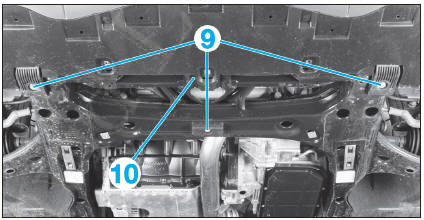
Fig. 44
- Except vehicles up to identification number J176282, unclip the condenser from the radiator and secure it so that it does not fall.
- Remove the radiator from below with the fan support.
INSTALLATION
Observe the following points:
- Vehicles up to identification number J176282: refill the air conditioning circuit,
- refill the cooling circuit and bleed it.
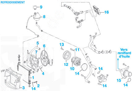
Cooling
- Radiator
- Radiator bleed screw
- Air guide
- Upper radiator hose
- Lower radiator hose
- Cooling fan motor
- Cooling fan motor support
- Expansion tank
- Cap
- Water pump
- Screw (replace): 1.2 daN.m
- Water pump pulley
- Screw: 1.3 daN.m
- Seal
- Thermostat housing
- Heater core.
Test yourself
A quick Mercedes-Benz B-Class quiz: every answer comes with an explanation and a link to the manual page.
Was this page helpful?