Diesel engines
Removing and refitting the powertrain
In this manual: Diesel engines
~2min read
ENGINE ' GEARBOX ASSEMBLY
REMOVAL
- Remove:
- the air filter housing,
- the underbody shields.
- Drain the following circuits:
- cooling system,
- engine.
- Remove:
- the front wheels,
- all cables and electrical connections attached to the engine and gearbox,
- the various hoses (air, vacuum, air conditioning, water, fuel, ...) connected to the engine accessories,
- the gearbox control cables (see the relevant 'GEARBOX' chapter).
- Lock the steering wheel, then remove the bolt from the steering column universal joint and separate the joint.
- Remove the air conditioning compressor (without opening the circuit) and hang it from the body.
- Remove the earth strap bolt from the oil sump.
- Manual gearbox vehicles: disconnect the clutch slave cylinder.
- Automatic gearbox vehicles: remove the oil hoses.
- Vehicles without particulate filter: remove the catalytic converter located under the vehicle.
- Vehicles with particulate filter: remove the particulate filter located under the vehicle.
- Support the engine cooling radiator.
- With xenon headlights: disconnect the height sensor connector and remove its mountings.
- Disconnect:
- the subframe anti-roll bar and anti-roll bar links,
- the steering tie rod from the hub carrier,
- the lower ball joint of the hub carrier,
- the driveshafts at the hubs.
- Place a support device under the subframe.
- Remove the subframe mounting bolts (1) and (2) (Fig. 70).
- Lower the subframe until the starter motor is accessible, then remove it.
- Lower the subframe with the engine ' gearbox assembly.
 Before lowering the subframe, make sure no wiring harness, hose or pipe will obstruct its descent.
- Remove the engine from the subframe (Fig. 71):
- remove the bearing bracket (3),
- pull the driveshafts out of the gearbox,
- fit a workshop crane with a chain engaged in the engine lifting eyes,
- lift the engine ' gearbox assembly until its weight is off the mounts,
- remove the rear rubber mount bolts (4),
- remove the front rubber mount nuts (5),
- remove the hose (6),
- lift the engine ' gearbox assembly and separate it from the subframe (7).
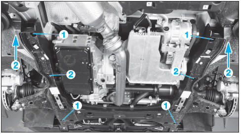
Fig. 70
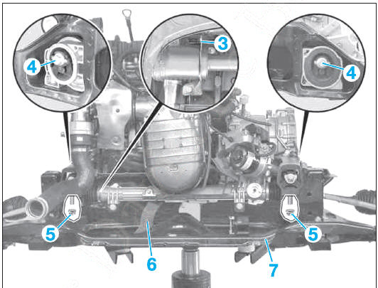
Fig. 71
INSTALLATION
Observe the following points:
- the guides on the subframe must engage in the holes in the side members,
- always replace self-locking nuts,
- observe the specified tightening torques,
- fill and top up the engine oil,
- fill and bleed the cooling system,
- bleed the clutch circuit,
- coat the contact points between the subframe and the crossmember with anti-corrosion paint,
- start the engine and check for leaks.
Test yourself
A quick Mercedes-Benz B-Class quiz: every answer comes with an explanation and a link to the manual page.
Was this page helpful?