Diesel engines
Lubrication circuit
In this manual: Diesel engines
30steps
~180min
4/5difficulty
Done 0 of 30
OIL PUMP
REQUIRED TOOLS
- [1]. Subframe retaining bolt (ref. 169 589 00 62 00) (Fig.30).
REMOVAL
- Lower the subframe:
- remove the air filter housing,
- the throttle actuator (vehicles with particulate filter) or the air intake throttle (vehicles without particulate filter),
- remove the steering column universal joint bolt, then separate the joint (lock the steering wheel),
- support the radiator,
- remove the engine undertray,
- move the rear of the wheel arch liners aside,
- unhook the rubber exhaust mountings,
- remove the earth strap bolt from the oil sump,
- with manual gearbox, unclip the clutch hydraulic control pipe from the gearbox and the bulkhead,
- with xenon headlamps, disconnect the height sensor connector and remove its mountings,
- fit a support device under the subframe,
- remove the 4 subframe mounting bolts (1) (Fig.30),
- in place of the subframe mounting bolts, fit the retaining bolts with the stops [1],
 Make sure the stops are centred on the retaining bolts.
- remove the 4 subframe mounting bolts (2),
- lower the subframe.
 Before lowering the subframe, make sure no wiring harness, hose or pipe will obstruct its descent.
- Drain the engine oil.
- Remove:
- the auxiliary drive belt (see relevant operation),
- the compressor and secure it to the body (without opening the circuit),
- the alternator,
- the auxiliary drive belt tensioner bracket,
- the catalytic converter,
- the oil dipstick tube.
- Disconnect the oil level sensor (3) (Fig.31).
- Place a workshop jack under the engine and raise it to relieve the rear engine mounts.
- Remove the mounting bolt (4) of the engine mount.
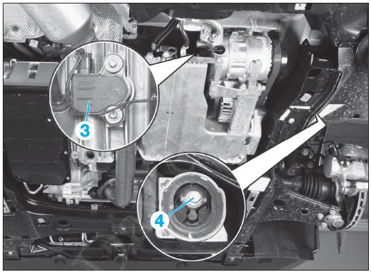
Fig. 31
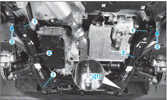
Fig. 30
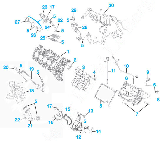
Lubrication
- Cylinder block
- Piston underside oil jet
- Oil deflector
- Bolt (M6): 1.2 daN.m
- Sealing gaskets
- Oil sump
- Bolt (M6):
- 1st stage: 0.6 daN.m
- 2nd stage: 1.3 daN.m.
- Drain plug: 3 daN.m
- Oil level, temperature and quality sensor: 0.5 daN.m
- Oil dipstick guide tube
- Oil dipstick
- Oil pump
- Bolt: 1.4 daN.m
- Suction pipe
- Oil pump drive chain
- Oil pump cover.
- Bolt (M6): 1.2 daN.m
- Turbocharger
- Turbo feed pipe
- Banjo bolt: 1.5 daN.m
- Turbo return pipe
- Bolt (M6): 0.8 daN.m
- Oil filter housing
- Oil cooler pipe
- Oil cooler
- Oil filter cartridge
- Oil filter cover: 2.5 daN.m
- Oil filler tube
- Oil filler cap
- Oil separator.
- Remove the oil pan (fig.33).
- Remove the oil pump chain cover (fig.32).
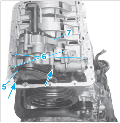
Fig. 32
- Remove the bolts (6) from the oil pump (7), then disengage the pump from its chain and remove it.
INSTALLATION
Reinstall the previously removed components, observing the following points:
- replace all sealing gaskets and clean the mating surfaces,
- before reinstalling, fill the oil pump with engine oil,
- observe the oil pan tightening sequence (Fig.33),
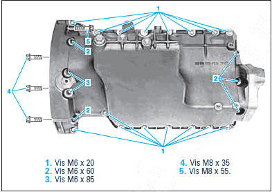
Fig. 33
- replace the tightening bolts where required,
- fill with engine oil and check the level.
CHECKING THE OIL PRESSURE
REQUIRED TOOLS
- Pressure gauge.
CHECK
- Set the coolant expansion tank (1) aside without disconnecting the hoses.
- Remove the bolt (2) from the oil filter housing (3) (Fig.34).
- Connect the pressure gauge with its adapter in place of bolt (2).
- Bring the engine to its normal operating temperature.
- Check the oil pressure at 80°C:
- ≥ 0.8 bar at idle.
- ≥ 3 bar at 2,000 rpm.
- ≥ 4 bar at 4,000 rpm.
- Stop the engine.
- Disconnect the pressure gauge.
- Refit bolt (2).
- Check the engine oil level.
- Check for oil leaks.
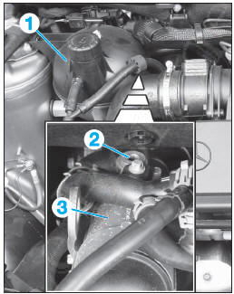
Fig. 34
Test yourself
A quick Mercedes-Benz B-Class quiz: every answer comes with an explanation and a link to the manual page.
Was this page helpful?