Diesel engines
Cylinder head operations
In this manual: Diesel engines
21steps
~126min
4/5difficulty
Done 0 of 21
 Before any work on the fuel system (supply, return or high pressure), strictly observe the recommendations given in 'Precautions to be taken' under the heading 'FUEL SUPPLY'
CAMSHAFTS
REQUIRED TOOLS
- [1]. Bracket retaining bolt (ref. 169 589 00 62 00) (Fig.61).
- [2]. Camshaft locking pin (ref. 111 589 03 15 00) (Fig.62).
REMOVAL
- Remove:
- the front right wheel,
- the engine undertray,
- the right wheel arch liner,
- the air filter housing,
- the pre-catalytic converter,
- the turbocharger (see relevant operation),
- the injection rail (see relevant operation),
- the injectors (see relevant operation).
- Remove the rocker cover in the reverse order of the sequence shown (Fig.59).
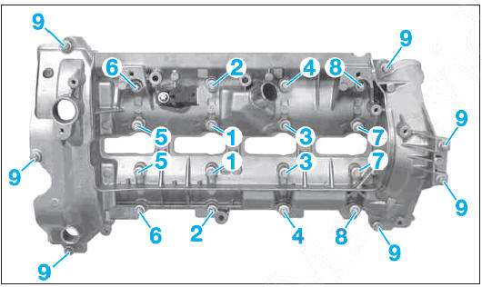
Fig. 59
 Cover the openings left exposed by removing the rocker cover with a clean cloth, especially the timing case opening and the injector openings.
- Remove the front cover with the vacuum pump (Fig.60):
- remove the bolts (1),
- pull the front cover (3) fitted with the vacuum pump (4) off the locating dowels (2).
 The front cover (3) must be removed with care, as the oil pipe (5) may deform and break in the cylinder head.
- Remove the high-pressure pump (see relevant operation).
- Lower the subframe:
- remove the throttle valve actuator (vehicles with particulate filter) or the intake air throttle (vehicles without particulate filter),
- remove the steering column universal joint bolt, then separate the joint (lock the steering wheel),
- support the radiator,
- remove the engine undertray.
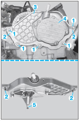
Fig. 60
- move the rear of the wheel arch liners aside,
- unhook the rubber exhaust mountings,
- remove the earth strap bolt from the oil sump,
- with manual gearbox, unclip the clutch hydraulic control pipe from the gearbox and the bulkhead,
- with xenon headlamps, disconnect the height sensor connector and remove its mountings,
- fit a support device under the subframe,
- remove the 4 bolts (6) securing the bracket (Fig.61),
- in place of the subframe mounting bolts, fit the retaining bolts with the stops [1],
 Make sure the stops are centred on the retaining bolts.
- remove the 4 bolts (7) securing the bracket,
- lower the subframe.
 Before lowering the subframe, make sure no wiring harness, hose or pipe will obstruct its descent.
- Turn the crankshaft to bring cylinder no. 1 to TDC. The mark (8) on the crankshaft pulley must line up with the one on the lower timing case (9) (Fig.62).
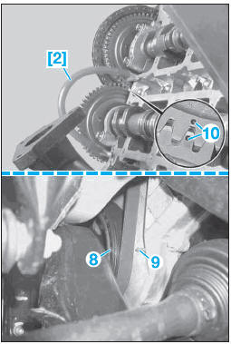
Fig. 62
- Make sure the marks (10) are correctly positioned.
These marks on the camshaft sprockets must be aligned with each other.
 If the camshaft timing marks do not line up, turn the crankshaft 2 additional full turns in the normal direction of engine rotation.
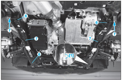
Fig. 61
- Remove the rear part of the right front wheel arch.
- Loosen the timing chain tensioner (11) from below and remove it upwards (Fig.63).
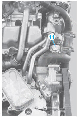
Fig. 63
Make alignment marks on the timing chain (12) and on the sprocket (13) (Fig.64).
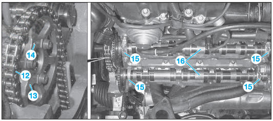
Fig. 64
- Secure the timing chain (12) to the camshaft sprocket with a plastic cable tie.
- Remove the sprocket (13) with the timing chain in place.
 Take care with the dowel pin (14).
- Remove the camshaft bearing caps (15) in successive stages and mark their positions.
- Remove the camshafts (16).
INSTALLATION
- Observe the following points:
- observe the specified tightening torques,
- replace all seals,
- Refit the camshafts, lubricating the contact surfaces with new engine oil,
- refit the camshafts with the marks (10) aligned with each other,
- fit the camshaft locking tool [2] (Fig.62),
- refit the sprocket (13) with the chain (12) onto the intake camshaft,
- remove the tool [2] and the plastic cable tie,
- refit the timing chain tensioner (11),
- turn the crankshaft two full revolutions and check the timing alignment (Fig.65),
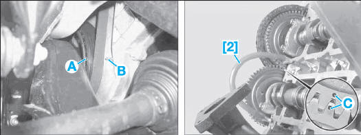
Fig. 65
- TDC mark on the pulley
- Mark on the lower timing case
- Camshaft alignment mark
[2]. Camshaft locking pin.
- refit the other components that were removed,
- start the engine and check that it runs correctly.
CYLINDER HEAD
REMOVAL
- Remove the engine and subframe assembly (see relevant operation).
- Remove:
- the pre-catalytic converter,
- the turbocharger (see relevant operation)
- the injection rail (see relevant operation),
- the injectors (see relevant operation).
- Remove the rocker cover in the reverse order of the sequence shown (Fig.59).
 Cover the openings left exposed by removing the rocker cover with a clean cloth, especially the timing case opening and the injector openings.
- Remove the front cover with the vacuum pump (Fig.60):
- remove the bolts (1),
- pull the front cover (3) fitted with the vacuum pump (4) off the locating dowels (2).
 The front cover (3) must be removed with care, as the oil pipe (5) may deform and break in the cylinder head.
- Remove (see relevant operation):
- the high-pressure pump,
- the camshafts.
- On the cylinder head, disconnect:
- the various vacuum hoses
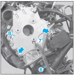
Fig. 66
- the various connectors,
- the various air and coolant hoses.
- Remove the rear cover (Fig.66):
- remove the hose (6),
- the bracket (7),
- the rear cover bolts (8), then the rear cover
 Take care with the dowel pins (arrows).
- Remove (Fig.67):
- the hose (9) from the EGR cooler (10),
- the oil dipstick guide (11),
- the hose (12) from the oil separator,
- the EGR pipe (13),
- the clamp (14),
- the upper hose clamp (15),
- the oil cooler (16) (10 bolts).
- Remove the coolant pipe (17) from the engine mount bracket (Fig.68).
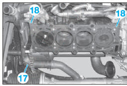
Fig. 68
- Remove the timing chain guide shoe.
- Remove the engine mounts from the subframe.
- Loosen the cylinder head bolts evenly, in several stages and in the reverse of the sequence shown in the figure (Fig.69).
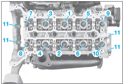
Fig. 69
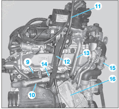
Fig. 67
- Lift the cylinder head off the centring sleeves (18) on the cylinder block (Fig.68) and place the cylinder head on wooden blocks on a workbench.
INSTALLATION
- Clean the mating surfaces of the cylinder head, cylinder block and front and rear covers. Use a chemical cleaner and do not use sharp tools that could damage the mating surfaces.
- Check that the centring sleeves are in place, then fit the new cylinder head gasket.
- Fit the cylinder head onto the cylinder block, then tighten the bolts evenly and in the sequence shown to the specified torque:
- tighten bolts (1) to (10) (M12) to 1 daN.m,
- tighten bolts (1) to (10) (M12) to 8 daN.m,
- tighten bolts (11) (M8) to 2 daN.m,
- tighten bolts (1) to (10) (M12) by 90°,
- check the tightness of bolts (11),
- tighten bolts (1) to (10) (M12) by a further 90°.
- For the rest of the refitting, observe the following points:
- replace the sealing gaskets,
- observe the specified tightening torques,
- fill, check the level and bleed the various circuits.
CYLINDER HEAD OVERHAUL
 This operation is carried out with the cylinder head removed.
SPECIAL POINTS FOR DISASSEMBLY
- During disassembly, take care to mark all parts and their pairing, if any, for reassembly.
- Disassemble each valve using a suitable valve spring compressor, making sure the tool is aligned with the valve axis and compressing the spring carefully. Remove the collets, the upper spring retainer and the spring.
- Clean the cylinder head and all the parts to be fitted to it.
- Clean and degrease the cylinder head mating surfaces and the bearing surfaces of the camshaft bearing caps. Use a chemical stripping product to dissolve traces of the old gasket and do not use sharp tools that could damage the mating surfaces.
- Using dye penetrant, check for any cracks on the contact surfaces of the intake and exhaust manifolds and the cylinder block.
- Check all wear parts, the surface condition of all mating surfaces and the operating clearances (see values and tolerances in the 'Specifications' section).
- Replace any parts outside tolerance or machine those that can be machined.
SPECIAL POINTS FOR REASSEMBLY
- Blow out all the cylinder head oil passages, especially those supplying lubrication to the camshafts.
- Lubricate all contact parts systematically with the recommended engine oil (valve stems, camshaft bearings, cam lobes, rocker arms, etc.).
- After refitting the valves, lightly tap each upper spring retainer with a mallet to seat the collets.
- Observe the specified tightening torques.
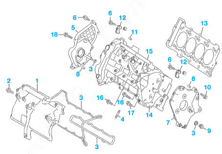
Cylinder head
- Cover plate
- Bolt: 3 daN.m
- Sealing gaskets
- Exhaust manifold stud
- Front housing
- Bolt: 1.2 daN.m
- Rear housing
- Dowel pin
- Cap
- Bolts:
- M6: 1.2 daN.m.
- M8: 2.6 daN.m.
- Locating dowels
- Camshaft bearing caps
- Cylinder head gasket
- Cylinder head
- Rocker cover
- Rocker cover bolts (M6 x 38): 1.2 daN.m
- Rocker cover bolts (M6 x 28): 1.2 daN.m
- Cylinder head bolts:
- M8 bolts: 2 daN.m.
- M12 bolts:
- 1st stage: 1 daN.m.
- 2nd stage: 8 daN.m.
- 3rd stage: 90°.
- 4th stage: 90°.
Test yourself
A quick Mercedes-Benz B-Class quiz: every answer comes with an explanation and a link to the manual page.
Was this page helpful?