Control cable
Exploded View
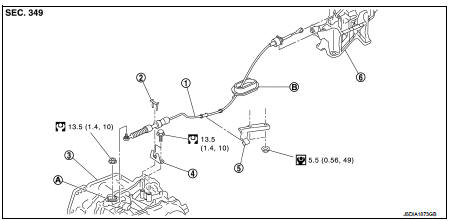
1. Control cable
2. Lock plate
3. Transaxle assembly
4. Bracket A
5. Bracket B
6. CVT shift selector assembly
A: Manual lever
B: Grommet
 : N·m (kg-m, ft-lb)
 : N·m (kg-m, in-lb)
Removal and Installation
INSTALLATION
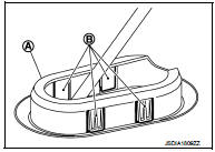
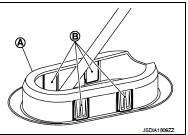
CAUTION:Always apply the parking brake before performing removal and installation. 1. Remove the battery. Refer to PG-124, "Removal and Installation". 2. Remove the control cable from the CVT shift selector assembly. Refer to TM-481, "Removal and Installation". 3. Disengage the pawls (B) of the grommet (A), and pull downwards to remove.
4. Remove the control cable installation nut from the manual lever.
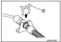
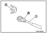
5. Remove the lock plate (1).
6. Remove sub muffler from the mounting rubber and lower the sub muffler downward. Refer to EX-12, "Exploded View". 7. Lift up the heat plate.
8. Remove the control cable (1) from the bracket (2).
 :Vehicle front
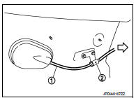
9. Remove the control cable from the vehicle.
10. Remove bracket.
INSTALLATION
Note the following, and install in the reverse order of removal.
• From below the vehicle, press the grommet (A) into place until the pawls (B) make a click sound.
CAUTION:• Place the grommet on the floor, then fasten it in place from below the vehicle.
• Check that pulling down on the grommet does not disconnect it.
• Pay attention to the following when connecting the control cable to the CVT shift selector.
1. When connecting the control cable (1) to the CVT shift selector assembly (2), face the grooved surface of the rib (A) up and insert the control cable until it stops.
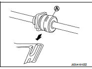
2. Install the socket (A) onto the CVT shift selector.
CAUTION:• Place the socket onto the CVT shift lever, then fasten it in place from above.
• Check that the pulling on the socket does not disconnect it.
Inspection
INSPECTION AFTER INSTALLATION
Check the CVT position. If a malfunction is found, adjust the CVT position. Refer to TM-383, "Inspection and Adjustment".