Transaxle & transmissioN CVT: RE0F11A
G sensor
In this manual: Transaxle & transmissioN CVT: RE0F11A
~1min read
Exploded View
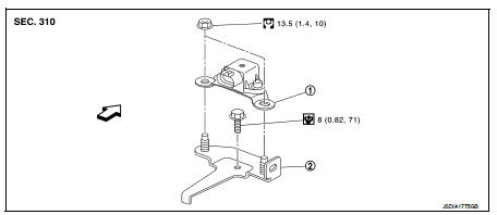
1. Bracket
2. G sensor
 : Vehicle front
 : N·m (kg-m, ft-lb)
 : N·m (kg-m, in-lb)
Removal and Installation
CAUTION:• Never drop or strike G sensor, because it has little tolerance for impact.
• Never use a power tool to avoid impact.
REMOVAL
1. Disconnect the battery cable from the negative terminal. Refer to PG-124, "Removal and Installation". 2. Remove driver seat (LHD) or passenger seat (RHD). Refer to SE-19, "Removal and Installation". 3. Remove center pillar lower garnish (left side) and dash side finisher (left side). Refer to INT-20, "CENTER PILLAR LOWER GARNISH : Removal and Installation" (center pillar lower garnish) and INT-20, "DASH SIDE FINISHER : Removal and Installation" (dash side finisher). 4. Pull up floor carpet. Refer to INT-23, "Removal and Installation". 5. Disconnect G sensor harness connector. 6. Remove G sensor.7. Remove bracket.
INSTALLATION
Installation is the reverse order of removal.
Adjustment
ADJUSTMENT AFTER INSTALLATION
Perform “G SENSOR CALIBRATION”. Refer to TM-377, "Description".
Was this page helpful?