Fluid cooler system
Exploded View
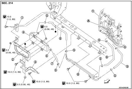
1. Bracket
2. Bracket
3. Bracket
4. CVT fluid cooler
5. Clamp
6. CVT fluid cooler hose C 7. CVT fluid cooler hose B 8. CVT fluid cooler tube assembly 9. CVT fluid cooler hose D 10. CVT fluid cooler hose A 11. Transaxle assembly
A. CVT oil warmer
 : Vehicle front
 : N·m (kg-m, in-lb)
Removal and Installation
REMOVAL
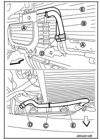
1. Remove front bumper assembly. Refer to EXT-13, "Removal and Installation". 2. Remove inlet air duct (lower). Refer to EM-161, "Removal and Installation". 3. Remove air guide (LH and RH). Refer to DLK-147, "HR16DE : Exploded View".4. Remove hose clamps (A) and fluid cooler hose B (B).
 : Vehicle front
5. Disconnect clip (C) from bracket.
6. Remove hose clamps (D) and fluid cooler hose C (E).
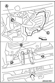
7. Remove nut (A) and bolts (B).
 : Vehicle front
8. Remove CVT fluid cooler (with brackets) (C) from the vehicle.
9. Remove clamps (A) and fluid cooler hose A (B).
 : Vehicle front
NOTE
:
Cap or plug openings to prevent fluid from spilling.
10. Remove clamps (C) and fluid cooler hose A (D).
NOTE:
Cap or plug openings to prevent fluid from spilling.
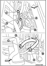
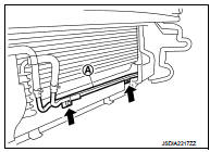
11. Remove CVT fluid cooler tube assembly (A) from the vehicle.
 : Bolt
INSTALLATION
Note the following, and Install in the reverse order of removal.
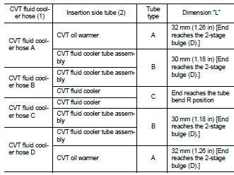
• Refer to the following when installing CVT fluid cooler hoses.

- Insert CVT fluid cooler hose according to dimension “L” described below.

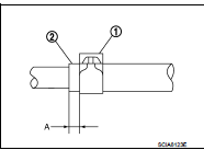
- Set hose clamps (1) at the both ends of CVT fluid cooler hoses (2) with dimension “A” from the hose edge.
Tube type A, B Dimension “A” : 5 – 9 mm (0.20 – 0.35 in) Tube type C Dimension “A” : 5 mm (0.20 in)
- Hose clamp should not interfere with the bulge of fluid cooler tube.
Inspection and Adjustment
INSPECTION AFTER INSTALLATION
Check for CVT fluid leakage. Refer to TM-480, "Inspection".
ADJUSTMENT AFTER INSTALLATION
Adjust the CVT fluid level. Refer to TM-379, "Adjustment".