Control Valve
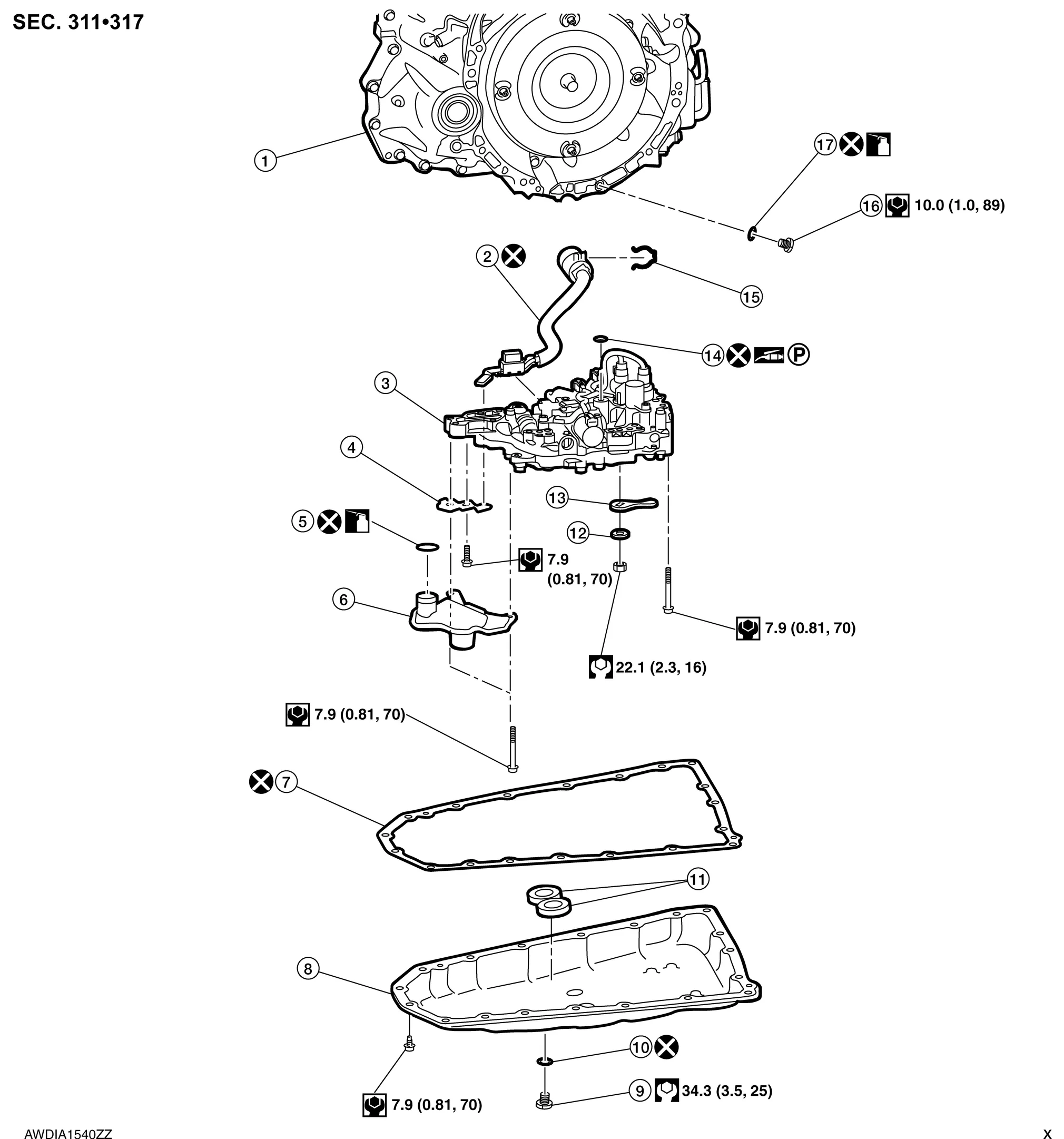
| 1. | Transaxle assembly | 2. | Terminal cord assembly | 3. | Control valve |
| 4. | Bracket | 5. | O-ring | 6. | Oil strainer assembly |
| 7. | Oil pan gasket | 8. | Oil pan | 9. | Drain plug |
| 10. | Drain plug gasket | 11. | Magnet | 12. | Spring washer |
| 13. | Manual plate | 14. | Lip seal | 15. | Snap ring |
| 16. | Overflow plug | 17. | O-ring | ||
 |
: Always replace after every disassembly. | ||||
 |
: N·m (kg-m, ft-lb) | ||||
 |
: N·m (kg-m, in-lb) | ||||
 |
: Apply petroleum jelly | ||||
 |
: Apply CVT fluid | ||||
Check that the part number and serial number of the new control valve (1) are identical to those of the attached CD (1).

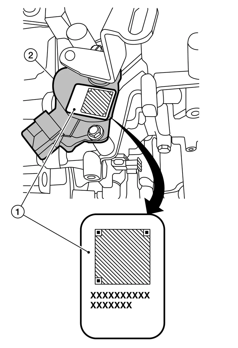
If old QR code sticker is affixed to transmission range switch, remove the QR code sticker and affix new QR code sticker included with new control valve.
REMOVAL
Disconnect battery negative terminal. Refer to Removal and Installation.
Remove drain plug from oil pan and then drain the CVT fluid.
Remove drain plug gasket.
Remove the oil pan bolts, and then remove the oil pan and oil pan gasket.
Remove the magnets from the oil pan.
Remove the lock nut (1), spring washer (2), and manual plate (3) from manual shaft (A).
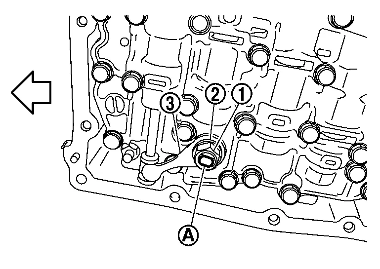
 |
: Front |
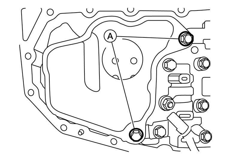
Remove the oil strainer assembly bolts (A) and remove the oil strainer assembly.
Remove CVT fluid temperature sensor bracket (1).
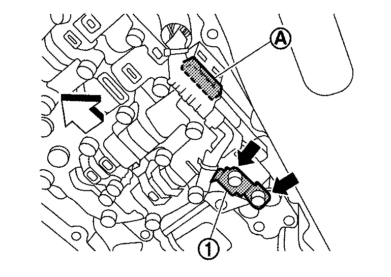
 |
: Bolt |
|
: Front |
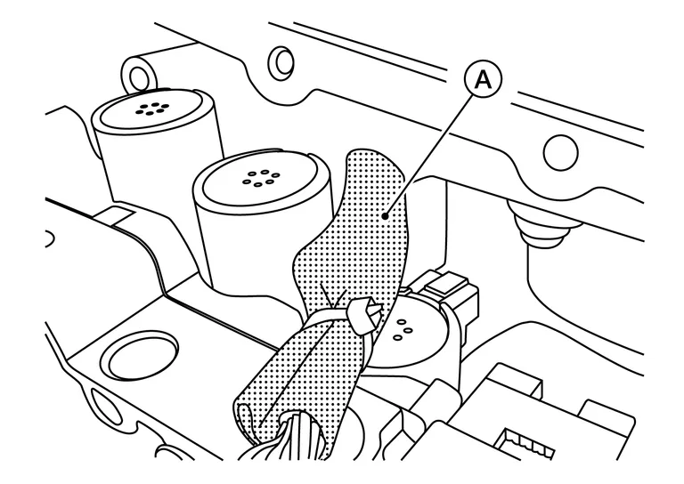
Disconnect control valve harness connector (A).
Remove the control valve bolts (A) and (B), and then remove the control valve from the transaxle case.
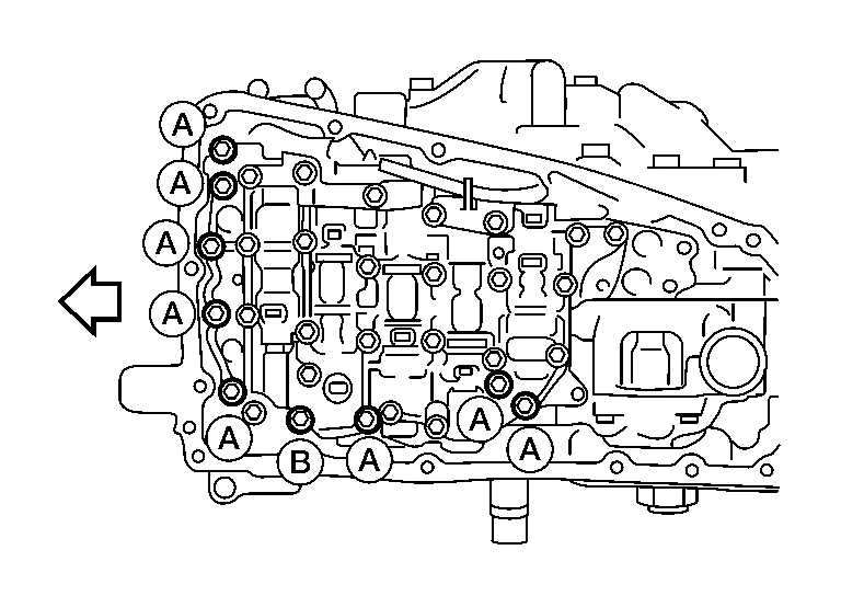
|
: Front |
Remove the lip seal (1) from the transaxle case.
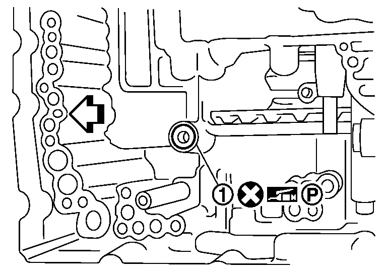
|
: Front |
INSTALLATION
Install the lip seal (1) to the transaxle case.
|
: Front |
Install the control valve to the transaxle case.
Secure the control valve using bolts (A), (B) and (C).
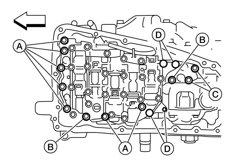
| Bolt | Bolt length mm (in) | Number of bolts |
|---|---|---|
| A | 54 (2.13) | 7 |
| B | 44 (1.73) | 2 |
| C | 25 (0.98) | 2 |
|
: Front |
Connect the control valve harness connector (A).
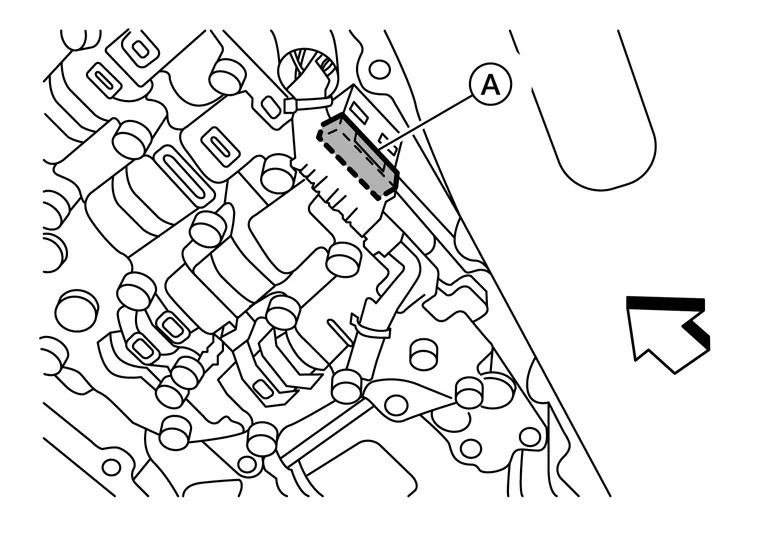
|
: Front |
Install the CVT fluid temperature sensor bracket to the valve body with bolt (A).
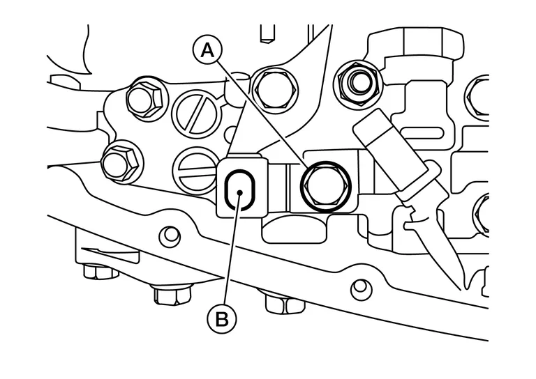
| Bolt | Bolt length mm (in) | Number of bolts |
|---|---|---|
| A | 54 (2.13) | 1 |
Install new O-ring to oil strainer assembly.
Install new oil strainer with bolts (A).
| Bolt | Bolt length mm (in) | Number of bolts |
|---|---|---|
| A | 54 (2.13) | 2 |
Install the manual plate (1) while aligning the ends as shown.
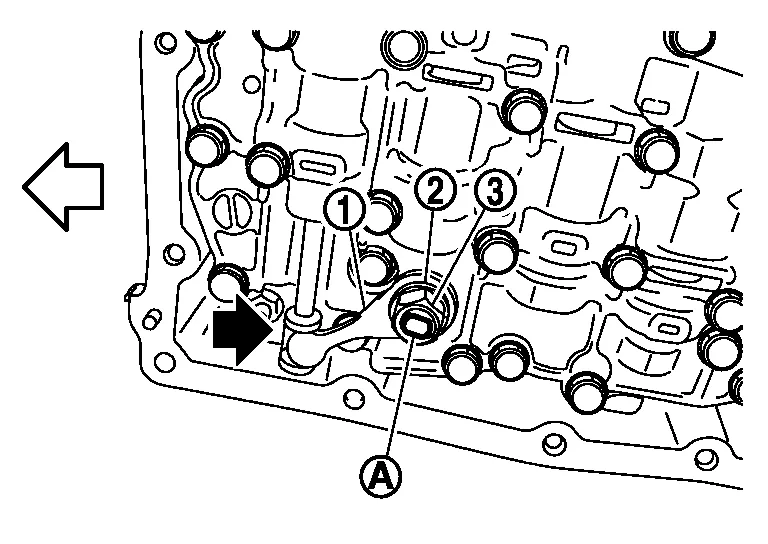
Align the slot of the manual plate with the manual shaft (A).
Align the end of the manual plate with the cutout of the manual valve.
|
: Cutout |
|
: Front |
Install the spring washer (2) and the lock-nut (3), and then tighten to the specified torque.
Install the magnets in the oil pan in their original location.
Install the oil pan to the transaxle case with the following procedure.Install the oil pan gasket to the oil pan.
Install the oil pan assembly to the transaxle case, and then temporarily tighten the oil pan bolts. Tighten the oil pan bolts in the order shown to the specified torque.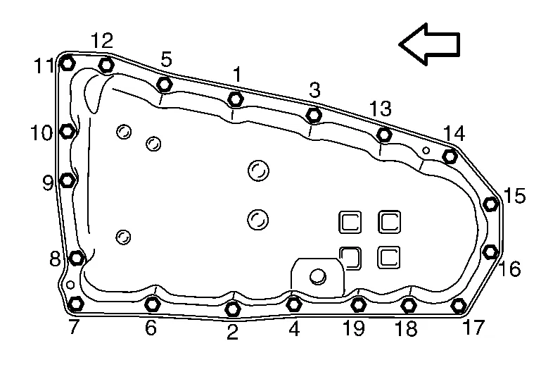
|
: Front |
Install drain plug gasket to drain plug.
Install drain plug to oil pan.
Install new QR code sticker (1) on Transmission Range (inhibitor) switch (2).
Flush the CVT fluid cooler and lines. Refer to CVT Fluid Cooler Flush.
Connect battery negative terminal. Refer to Removal and Installation.
Fill the transaxle assembly with CVT fluid. Refer to Refilling.
INSPECTION AFTER REMOVAL
Check oil pan for foreign material.
If a large amount of worn material is found, clutch plate may be worn.
If iron powder is found, bearings, gears, or clutch plates may be worn.
If aluminum powder is found, bushing may be worn, or chips or burrs of aluminum casting parts may enter.
Check points where wear is found in all cases.
INSPECTION AFTER INSTALLATION
Check the CVT fluid level and leakage. Refer to Inspection.
ADJUSTMENT AFTER INSTALLATION
Perform "ADDITIONAL SERVICE WHEN REPLACING CONTROL VALVE." Refer to Description.