Transmission & Driveline
Water Hose
In this manual: Transmission & Driveline
~2min read
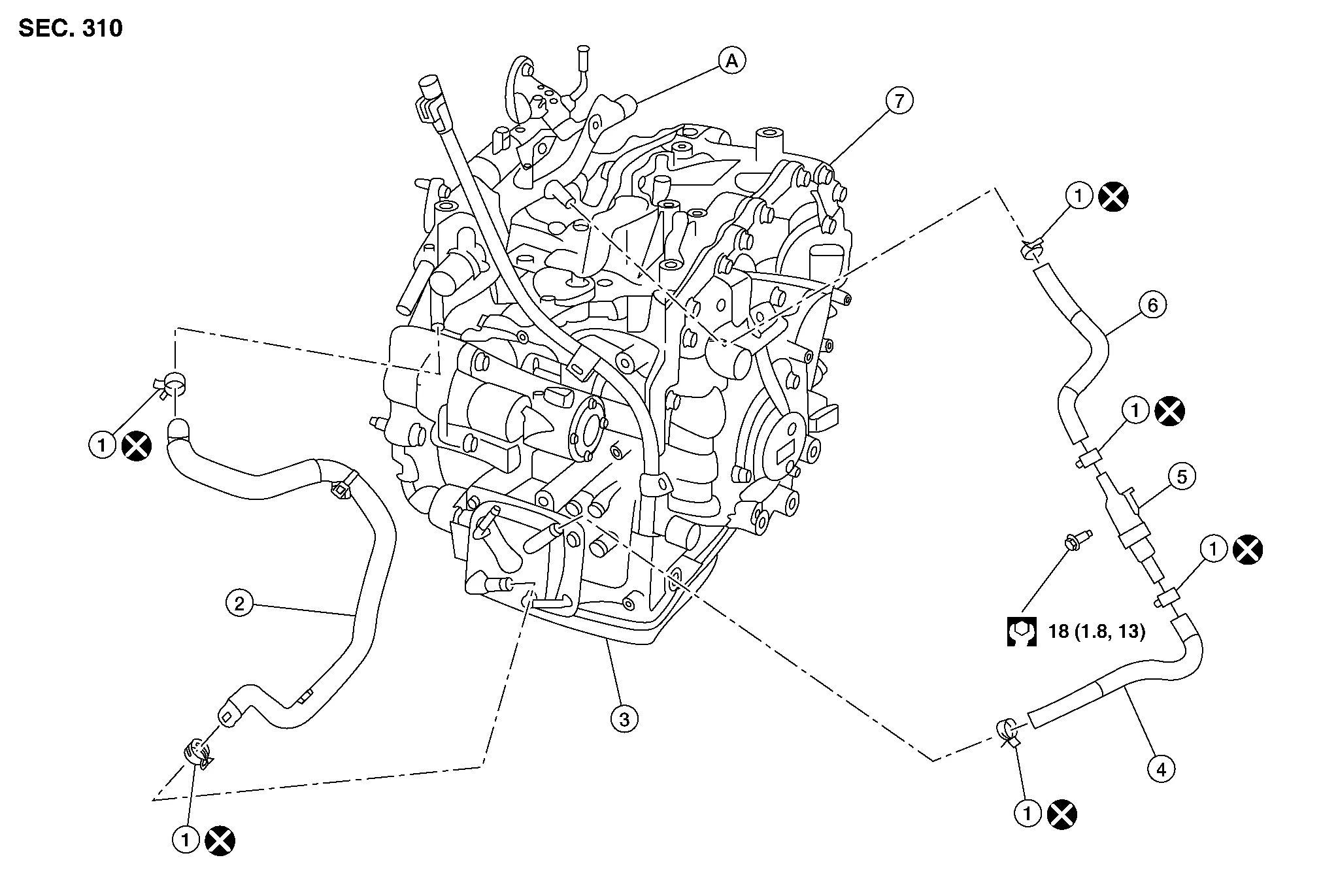
| 1. | Hose clamp | 2. | CVT water hose A | 3. | Transaxle assembly |
| 4. | CVT water hose B | 5. | Heater thermostat | 6. | CVT water hose C |
| 7. | Transaxle assembly | A. | Water outlet |
REMOVAL
Drain engine coolant from radiator. Refer to Changing Engine Coolant.
Remove front air duct. Refer to Exploded View.
Remove hose clamps, and remove CVT water hose A.
Remove hose clamps, and remove CVT water hose B.
Remove hose clamps, and remove CVT water hose C.
INSTALLATION
Installation is in the reverse order of removal.
Hose clamp should not interfere with the spool or bulge.
*Refer to the following when installing CVT water hose.
| Water hose (1) | Installation side tube (2) | Direction of paint mark | Hose insertion depth |
|---|---|---|---|
| CVT water hose A | Water outlet | Upward | End reaches the 2-stage bulge. |
| CVT oil warmer | Frontward | ||
| CVT water hose B | CVT oil warmer | Frontward | |
| Heater thermostat | Align with the mark on the heater thermostat side | ||
| CVT water hose C | Heater thermostat | Align with the mark on the heater thermostat side | End reaches the expansion part. |
| Water outlet | Upward | End reaches the 2-stage bulge. |
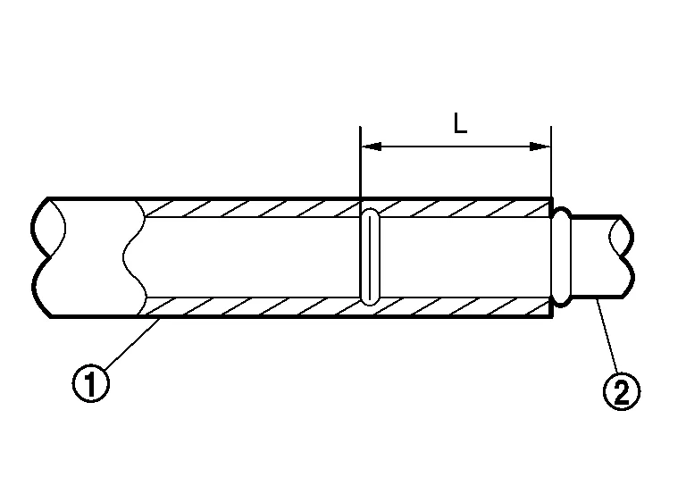
| CVT Water hose (1) | Installation side tube (2) | Hose clamp (3) | |
|---|---|---|---|
| Direction of tab* | Clamping position* | ||
| CVT Water hose A | Water outlet | C | A: 5-7 mm (0.20 - 0.28 in) (L) from hose end. |
| CVT oil warmer | J | ||
| CVT Water hose B | CVT oil warmer | H | B: Align with the paint mark (C) as shown. |
| Heater thermostat | A | ||
| CVT Water hose C | Heater thermostat | A | |
| Water outlet | G | ||
*Refer to the following when installing hose clamps.
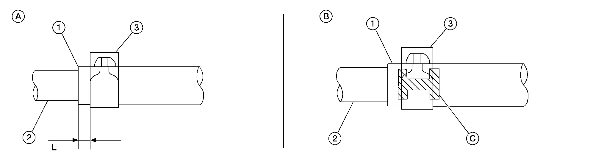
The illustrations indicate the view from the hose ends.
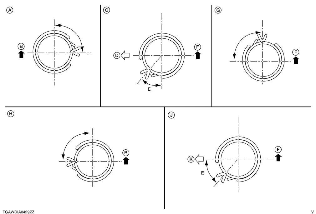
B. Front of Nissan Murano vehicle D. Vehicle right E. 45° F. Top of Nissan Murano vehicle K. Front of vehicle When installing hose clamps, the center line of each clamp tab should be positioned as shown.
Start and warm up the engine.
Visually check that there is no leakage of engine coolant and CVT fluid.
Was this page helpful?