Repair bench
A - REAR FRONT SUBFRAME MOUNTING
This is the main front reference point.
Right-hand side
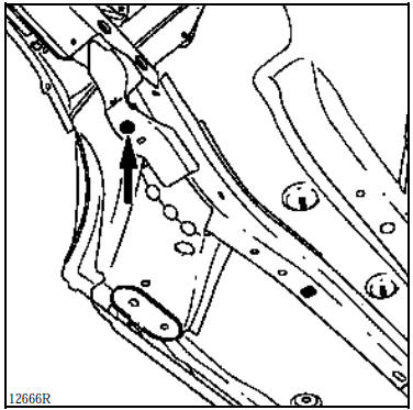
Left-hand side
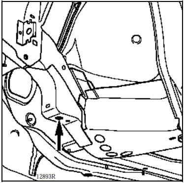
1 - Front mechanical components removed
The gauge rests under the rear section of the side member and is centred in the subframe mounting hole.
NOTE:
on the left side, the hole is round,
on the right side, it is a slot.
I - MAIN ALIGNMENT REFERENCES
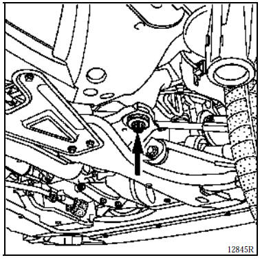
2 - Front mechanical unit in place
The gauge fits over the subframe mounting bolt and rests on the washer of the mounting bolt.
NOTE: the two sides are not symmetrical; on the right side, the mounting uses a Silentbloc bushing.
In the event of rear restructuring, these two points alone are sufficient for alignment and support of the front of the vehicle.
I - MAIN ALIGNMENT REFERENCES (continued)
B - REAR SUSPENSION FRONT POINT
This is the main rear reference.
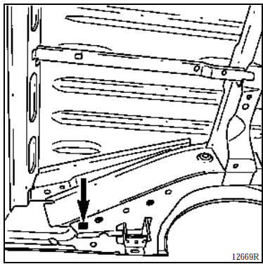
Without mechanical unit
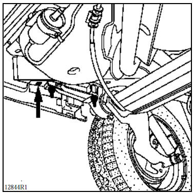
With mechanical unit
Rear mechanical unit in place or removed
The gauge rests under the side member and is centred in the (square) hole.
In the event of front restructuring, these two points alone are sufficient for alignment and support of the rear of the vehicle.
II - SUPPLEMENTARY ALIGNMENT REFERENCES
These are temporary references intended to replace the main ones when the latter have been affected by the impact.
G - REAR PART OF FRONT SIDE MEMBER
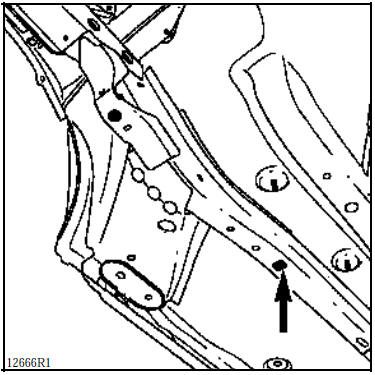
This point also serves as a positioning reference when replacing the rear part of a front side member.
On the impact side, this point is used to support the vehicle in addition to a main reference on the opposite side.
NOTE: these points should only be used in the cases mentioned above; there is no need to set them up when the main references (points A and B) are correct.
This supplementary reference function can also be performed by the front side member end checking points for a rear impact, and vice versa.
III - POSITIONING REFERENCES FOR REPLACED PARTS
C - FRONT SUBFRAME FRONT MOUNTING
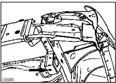
1 - Front mechanical components removed
The gauge rests under the front subframe support and is centred in the hole with the mounting bolt.
It is to be used when replacing:
the front end crossmember,
a partial side member,
a front-end half-assembly.
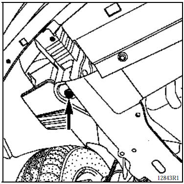
2 - Front mechanical unit in place
The gauge fits over the subframe mounting bolt and washer.
It is used:
in a front impact for a minor collision,
for a diagnosis of the front section checking.
III - POSITIONING REFERENCES FOR REPLACED PARTS (continued)
E - REAR SHOCK ABSORBER UPPER MOUNTING
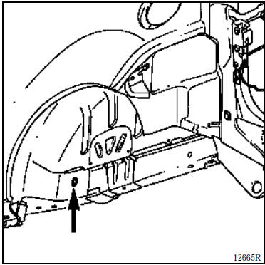
The gauge sits in the location of the shock absorber clevis and is used to position this mounting when replacing:
a rear side member,
the rear floor unit.
It is also to be used during straightening.
F - FRONT SHOCK ABSORBER UPPER MOUNTING
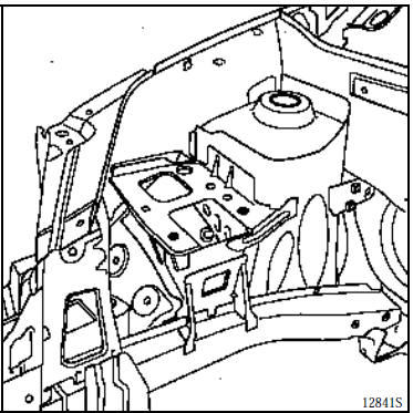
The gauge rests under the shock absorber cup and centres in the shock absorber mounting hole.
It is to be used when replacing:
a wheel arch section,
a front-end half-assembly.
It is also to be used during straightening.
III - POSITIONING REFERENCES FOR REPLACED PARTS (continued)
P - FRONT AND REAR ENGINE MOUNTING
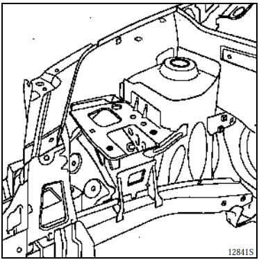
The gauge is placed over the engine mount; it centres in the engine mount mounting holes.
It is used with the mechanical unit removed when replacing a front-end half-assembly.
J - REAR END OF REAR SIDE MEMBER
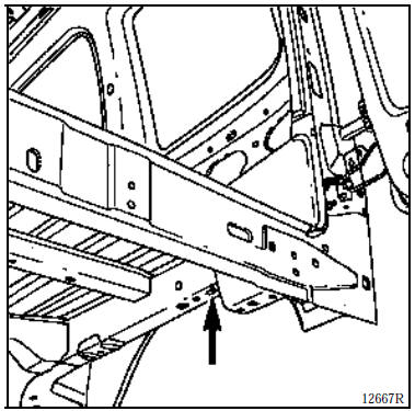
The gauge rests under the side member and is centred in the pilot hole (slot).
It can be used for a minor rear impact without removing the rear suspension, but requires removal of the exhaust mounting.
III - POSITIONING REFERENCES FOR REPLACED PARTS (continued)
L - REAR END CROSSMEMBER (VALANCE)
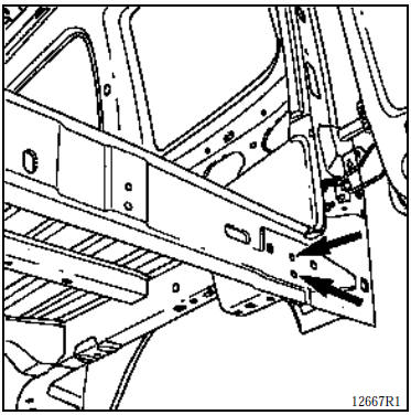
The gauge is used to position the crossmember; it rests vertically against the valance crossmember, then centres in the energy absorber bracket mounting hole.
It is used when replacing the complete rear valance assembly, with or without mechanical unit.
K - FRONT END CROSSMEMBER
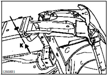
The gauge is used to position the crossmember; it rests vertically against the front end crossmember, then the crossmember is centred using a centring bolt at (K).
1 - Front mechanical components removed
It is used when replacing the front end crossmember, with or without mechanical unit.
NOTE: replacing the front end crossmember is performed without removing the powertrain, but requires removal of the radiator.
2 - Front mechanical unit in place
The gauge is used for checking the front crossmember.
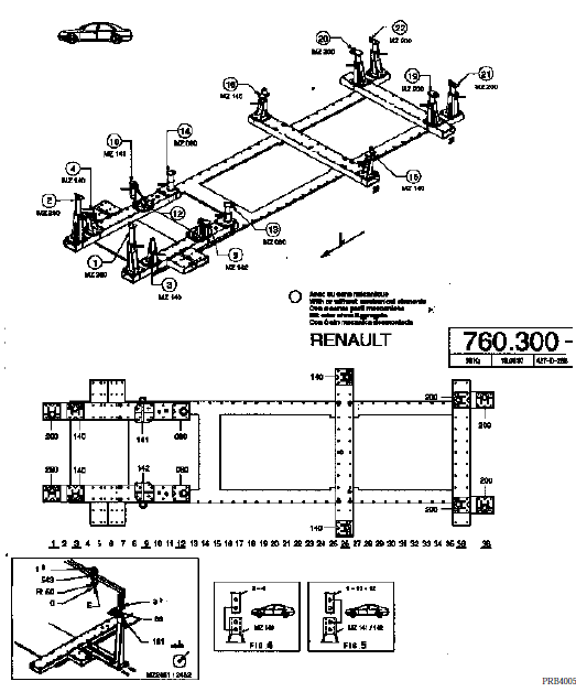
CELETTE REPAIR BENCH
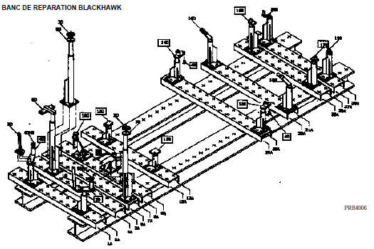
BLACKHAWK REPAIR BENCH
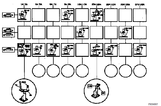
IV - SPECIAL TOOL REFERENCES
BLACKHAWK
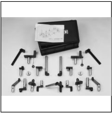
Specific heads for MS system
Order from: BLACKHAWK S.A.
Centre Eurofret
Rue de Rheinfeld
67100 STRASBOURG
Supplier reference: REN 88200
CELETTE
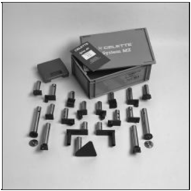
Specific heads for MS system
Order from: CELETTE S.A.
B.P. 9
38026 VIENNE
Supplier reference: 760 300
Test yourself
A quick Renault Kangoo quiz: every answer comes with an explanation and a link to the manual page.