Method symbols
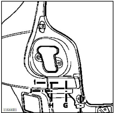
The drawing above shows the locations on the vehicle for which a sheet metal joint section is represented by the diagrams that
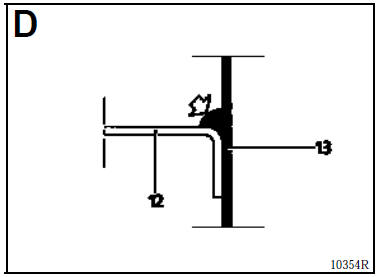
 This line defines the axis of the sections.
The point defines the exact location of the weld joint.
 This letter designates the diagram corresponding to the section (it is shown in one of the upper corners of each diagram).
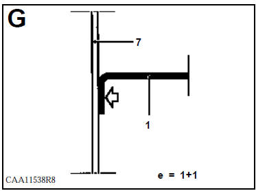
The section diagrams contain the following indications:
 The black part is the one that will be removed in the operation.
 are the reference numbers of the parts corresponding to the list on the page.
 are the thicknesses (in mm) of the sheet metal considered for resistance spot welding.
 This arrow in the diagram indicates the access side for unclinching the spot welds (see special cases).
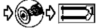
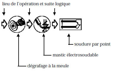
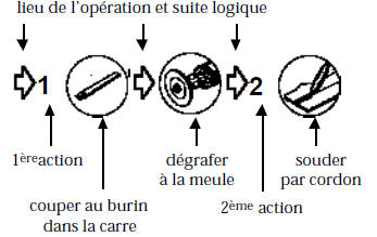
It also indicates the logical sequence of operations in the symbols located under each diagram.
Example:
SPECIAL CASES
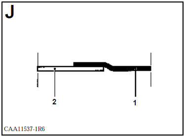
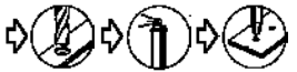
In this example, access for removing part 1 is not direct. The spot welds will be unclinched through part 2, which is to be retained.
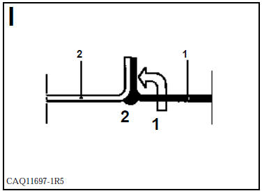
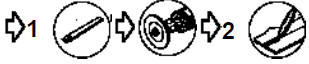
 This arrow indicates that the part it passes through must be cut before
access to the joint.
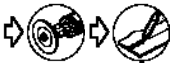
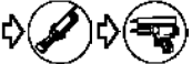
The following markings indicate different operations:
unclinching
welding
Under diagram I
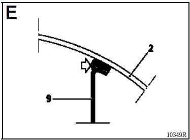
 In this special case, the arrow indicates that the joint is made by arc stud welding (MAG).
 In this example, the joint is made by bonding.
Test yourself
A quick Renault Kangoo quiz: every answer comes with an explanation and a link to the manual page.