Fault location tree
| ALP 1 | No communication with the ECU |
Check that the vehicle type and domain selected on your tool are correct. Make sure the tool is not faulty by trying to communicate with an ECU on another vehicle. Check the power supply to the diagnostic socket: + Before ignition on, pin 16 / + After ignition on, pin 1 / Ground on pins 4 and 5. Check (according to the wiring diagram and equipment):
Disconnect the engine control unit (ECU) and check that there are no conductive elements on the ECU pins. If removal reveals any contamination, clean or repair it and try to establish communication. If the fault persists, connect the terminal block ref: Elé. 1681 to the engine harness. Check continuity and the absence of parasitic resistance on the following connections: ECU connector A pin B4 → Diagnostic socket pin 7 (K-line) Check the power supplies for conformity: ECU connector B pin E3 → + After ignition, By bypassing the normally open contact of the injection unit power relay, i.e. pins 3 and 5 of the relay holder: ECU connector B pins M3 and M2 → + 12 V battery (via test jumper) Check the continuity of the connection between: ECU connector B pin D4 → pin 2 of the injection unit power relay holder. |
Try to establish communication with another control unit in the same vehicle.
Air conditioning, airbag, anti-lock brakes - dynamic stability control, body control module (BCM), instrument panel, communication unit, parking assistance. Try to establish communication after each disconnection. If communication is established after a disconnection, carry out the diagnosis of the control unit concerned.
STEP 2Replace the engine control unit. If necessary, modify the configuration of the new unit to match the options fitted to the vehicle. WARNINGIf the "IMA" function is in service, follow the ECU replacement procedure defined in the "Help: IMA Calibration" section of this note. |
AFTER REPAIR
Carry out a road test, then a check with the diagnostic tool.
| ALP 2 | Starting problems (or no start) |
INSTRUCTIONS
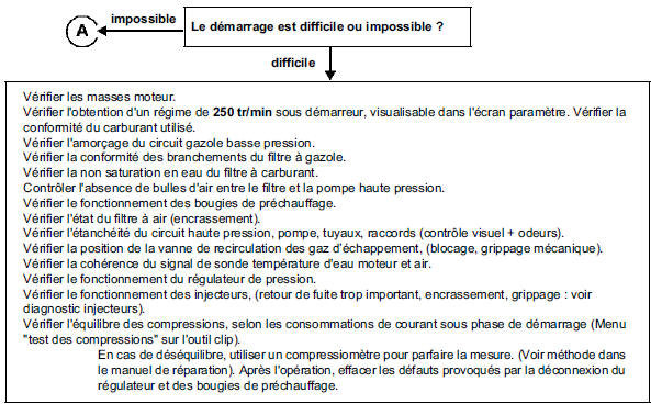
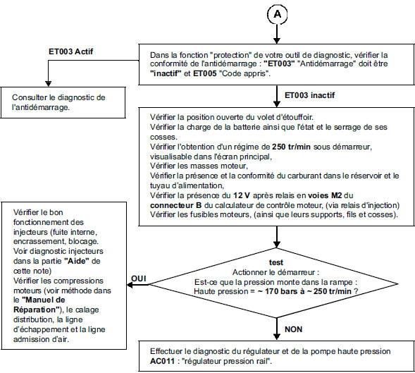
Before carrying out this customer effect, make sure there is no fault and check whether the "parameters" and "states" are correct (or not) using the diagnostic tool.
If the customer effect is not eliminated, carry out the following checks.
AFTER REPAIR
Carry out a road test, then a check with the diagnostic tool.
| ALP 3 | Injection noise |
INSTRUCTIONS
Before carrying out this customer effect, make sure there is no fault and check whether the "parameters" and "states" are correct (or not) using the diagnostic tool.
If the customer effect is not eliminated, carry out the following checks.
| If the "IMA" function is in service: check the authenticity of the codes by comparing the injector codes assigned to each cylinder with those engraved on each injector. |
| If the injection noise occurs after a cold start: Check priming of the low-pressure fuel circuit. Check the power supply to the fuel heater. Check the operation of the glow plug (preheating) system. Check that the fuel and engine temperatures are consistent. If the effect persists, check the rail pressure and carry out diagnosis AC004: "Boost pressure solenoid valve" and AC011: "Rail pressure regulator". |
| If the injection noise occurs at idle: check the condition of the terminals on the injector and pressure regulator connectors. Check the conformity of the air flow information (use diagnostic PR050). Check that the position of the exhaust gas recirculation (EGR) valve is correct (use diagnostic AC002): "EGR solenoid valve". If the effect persists, carry out the injector diagnosis (see the "Help" section). If the injection noise occurs at all engine speeds: carry out an injector diagnosis (see the "Help" section). Check the condition of the terminals on the injector and pressure regulator connectors. Check that the fuel is correct. Check the conformity of the air flow information (use diagnostic PR018: "Estimated air flow" and PR131: "EGR air flow deviation"). If the effect persists, check the rail pressure and carry out diagnosis AC004 "Boost pressure solenoid valve" and AC011: "Rail pressure regulator". |
| If the injection noise occurs during transient engine speed changes: in case of engine surging during gear changes, check the clutch switch for correct operation. During a road test, when changing gear, monitor parameter PR202 (CP3) or PR097 (CP1). If it varies without noticeable influence on the rail pressure, carry out diagnosis AC011: "Rail pressure regulator". If the effect persists, carry out the injector diagnosis (see the "Help" section of this note). |
AFTER REPAIR
Carry out a road test, then a check with the diagnostic tool.
| ALP 4 | Lack of power |
INSTRUCTIONS
Before carrying out this customer effect, make sure there is no fault and check whether the "parameters" and "states" are correct (or not) using the diagnostic tool.
If the customer effect is not eliminated, carry out the following checks.
WARNING: If overheating exceeds 119 °C, the ECU deliberately limits fuel flow (the overheating warning light comes on from 115 °C). If the "IMA" function is in use: check the authenticity of the codes by comparing the injector codes assigned to each cylinder with those engraved on each injector.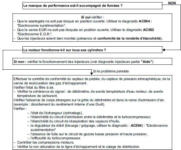
AFTER REPAIR
Carry out a road test, then a check with the diagnostic tool.
| ALP 5 | Rough engine running |
INSTRUCTIONS
Before carrying out this customer effect, make sure there is no fault and check whether the "parameters" and "states" are correct (or not) using the diagnostic tool.
If there are jerks or over-revving during gear changes, check the clutch switch for correct operation. If the effect persists:- Check that the fuel used is correct.
- Check priming of the low-pressure fuel circuit. Also check that the diesel filter is correctly connected and not saturated with water.
- Check that there are no air bubbles between the filter and the high-pressure pump.
- Check that the rail pressure is correct (engine warm):
+/- 25 bar around the rail pressure value at idle (variations between minimum and maximum rail pressure at idle must not exceed 50 bar).
~ 1350 bar under load with accelerator pedal fully depressed.
If there is an anomaly, carry out diagnosis AC004: "Boost pressure solenoid valve".
- Check the conformity of the air flow, use diagnostic PR018: "Estimated air flow".
If the effect persists:
- Check the injectors: with the engine running at idle, disconnect the injectors one after the other:
Replace the injector whose disconnection causes no change in engine operation.
Clear the faults caused by multiple disconnections, then carry out a road test to confirm the repair.
- Check engine compressions.
AFTER REPAIR
Carry out a road test, then a check with the diagnostic tool.
Test yourself
A quick Renault Megane quiz: every answer comes with an explanation and a link to the manual page.