Interpreting states
| ET001 | + AFTER IGNITION COMPUTER |
ET001 ABSENT ignition on
| Check the power supply fuse FD (5A) of the protection and switching unit. Using a multimeter, check for +12 V ignition on at the fuse holder. Repair if necessary. |
| Using a multimeter and the battery +12 V, check for ground continuity on the following links: Pin G4 black connector A, 48-way injection computer → Battery ground Repair if necessary. |
| If the voltage is zero, check the continuity and the insulation to ground of the following link: Pin D1 black connector A, 48-way injection computer → Pin 1 protection and switching unit Repair if necessary. |
ET001 PRESENT ignition on
Using a multimeter, check that there is no +12 V with ignition off at pin 1 of the protection and switching unit.Repair if necessary.
AFTER REPAIR
Carry out a new system diagnosis.
Deal with any other faults.
Erase the stored faults.
| ET003 | IMMOBILISER |
ET003 ACTIVE
Refer to the Cabin Central Unit Diagnosis Note.
ET003 INACTIVE
Refer to the Cabin Central Unit Diagnosis Note.
AFTER REPAIR
Carry out a new system diagnosis.
Deal with any other faults.
Erase the stored faults.
| ET004 | AIR CONDITIONING AUTHORISATION |
| YES | The air conditioning authorisation only changes to YES if the driver has requested air conditioning: air conditioning switch in AC or AUTO position with the fan at minimum. State ET018: "air conditioning request" will change to YES if these conditions are met, and will then allow state ET004: "air conditioning authorisation" to change. |
| NO | State ET004 remains at NO with ignition on, even though the air conditioning request switch is activated. The vehicle must be at idle for state ET018: "Air conditioning request" to change to YES, so that state ET004 also changes to YES and the air conditioning can operate. |
If state ET004 remains at NO and the switch is engaged, check:
If the pressure appears inconsistent, refer to the fault DF049: "Refrigerant pressure sensor circuit" and follow the recommended procedure. If other faults appear in the air conditioning area, refer to the "Air Conditioning" Diagnosis Note which covers these faults. |
AFTER REPAIR
Carry out a new system diagnosis.
Deal with any other faults.
Erase the stored faults.
| ET006 | CODE LEARNED |
| YES | The code changes to YES if communication between the cabin central unit computer and the injection computer is possible and the badge code is recognised. Engine start authorisation is only given if the code is correctly recognised by the cabin central unit computer and state ET003: "Immobiliser" changes to INACTIVE. |
| NO | The code remains at NO if communication between the cabin central unit computer and the injection computer is impossible, and state ET003: "Immobiliser" remains ACTIVE. The cause may be keys that were incorrectly learned; in this case refer to the cabin central unit Diagnosis Note and carry out a multiplex network test (if the diagnosis was carried out by functions), and make sure that communication between the cabin central unit, the protection and switching unit and the injection computer is present. If communication is not established, contact your techline. |
AFTER REPAIR
Carry out a new system diagnosis.
Deal with any other faults.
Erase the stored faults.
Return to the conformity check.
| ET007 | GLOW PLUG UNIT CONTROL |
| YES | When starting the vehicle cold, the injection computer controls the glow plug unit so that the vehicle can start; the state must change to YES during the starting phase. If the vehicle does not start and state ET007 correctly changes to YES during engine starting, check:
If the vehicle starts and state ET007 remains at YES during engine running, refer to the fault interpretation chapter for DF017: "Glow plug relay control circuit" and DF025: "Glow plug unit diagnostic link". |
| NO | After the vehicle starts, the injection computer must stop controlling the glow plug unit; the state must change to NO during engine running. If the vehicle does not start, the state remains at NO and preheating was not carried out during the starting phase, check the following links: Injection computer pin A4 grey connector C, 32-way → Pin 9 glow plug unit Repair if necessary. |
AFTER REPAIR
Carry out a new system diagnosis.
Deal with any other faults.
Erase the stored faults.
| ET012 | PRIMARY BRAKE SWITCH |
WARNING: States ET012 and ET013 are directly linked.
STATE 012: "INACTIVE", brake pedal pressed
If the stop lights work:- Check the continuity and the absence of parasitic resistance between:
Injection computer grey 32-way connector C, pin E4 → Pin 3 brake light switch. Repair if necessary.
If the stop lights do not work:
- Check the condition and installation of the brake switch as well as the brake light fuse.
- Remove and test the operation of the brake switch:
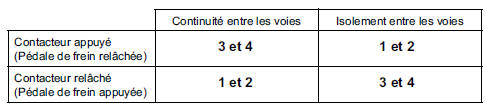
- Replace the brake switch if necessary.
- Check and confirm the ignition-switched + (after ignition) is present on pins 2 and 4 of the brake switch connector.
AFTER REPAIR
Carry out a new system diagnosis.
Deal with any other faults.
Erase the stored faults.
WARNING: States ET012 and ET013 are directly linked.
STATE 012: "ACTIVE", brake pedal released.
If the stop lights work:- Check the continuity and the absence of parasitic resistance between:
Injection computer grey 32-way connector C, pin E4 → Pin 3 brake light switch. Repair if necessary.
If the stop lights do not work:
- Check the condition and installation of the brake switch as well as the brake light fuse.
- Remove and test the operation of the brake switch:
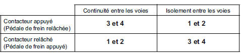
- Replace the brake switch if necessary.
- Check and ensure the presence of +after ignition on pin 1 of the brake light switch connector.
AFTER REPAIR
Carry out a new system diagnosis.
Deal with any other faults.
Erase the stored faults.
| ET014 | FAN MOTOR 1 CONTROL |
INSTRUCTIONS
State ET014: "Fan motor 1 control" is directly linked to state ET022: "Low speed fan motor request".
| ROTATING | When the cooling fan starts to operate and the coolant temperature is 90 ˚C (engine hot) or the air conditioning is operating, state ET022: "Low speed fan motor request" changes to ACTIVE and state ET014: "Fan motor 1 control" changes to ROTATING. If the cooling fan does not operate, check:
Make sure there is continuity between the following pins: Pin 1 of the cooling fan unit → Pin M1 of connector P1 of the Protection and Switching Unit (49R3) Check that the low-speed resistor of the cooling fan unit is 0.69 Ω. Replace the resistor if its value is not as specified. Refer to the cooling fan unit diagnosis in the Diagnostic Note "Protection and Switching Unit" for more details. |
If the Protection and Switching Unit no longer detects the frames from the injection ECU, cooling fan unit 1 will run until the battery is completely discharged.
If cooling fan unit 1 fails, cooling fan unit 2 is then activated.
AFTER REPAIR
Carry out a new system diagnosis.
Deal with any other faults.
Erase the stored faults.
| STOPPED | When the engine temperature has dropped sufficiently (X < 90 °C) or the air conditioning is switched off, state ET022: "GMV low-speed request" changes to INACTIVE and, as a result, state ET015: "GMV 2 control" changes to STOPPED. |
If the Protection and Switching Unit no longer detects the frames from the injection ECU, cooling fan unit 1 will run until the battery is completely discharged.
If cooling fan unit 1 fails, cooling fan unit 2 is then activated.
AFTER REPAIR
Carry out a new system diagnosis.
Deal with any other faults.
Erase the stored faults.
| ET015 | GMV 2 CONTROL |
INSTRUCTIONS
State ET015: "GMV 2 control" is directly linked to state ET022: "GMV low-speed request".
| ROTATING | Cooling fan 2 starts when cooling by cooling fan unit 1 is insufficient or when the air conditioning is running. State ET021: "GMV high-speed request" changes to ACTIVE and state ET015: "GMV 2 control" changes to RUNNING. If the fan does not run, check:
Make sure there is continuity between the following pins: Pin 1 of the cooling fan unit → Pin M1 of connector P1 of the Protection and Switching Unit (49R3) Refer to the cooling fan unit diagnosis in the Diagnostic Note "Protection and Switching Unit" for more details |
| STOPPED | When the engine temperature has dropped sufficiently (X < 90 °C), state ET021: "GMV high-speed request" changes to INACTIVE and, as a result, state ET015: "GMV 2 control" changes to STOPPED. |
If the Protection and Switching Unit no longer detects the frames from the injection ECU, cooling fan unit 1 will run until the battery is completely discharged.
If cooling fan unit 1 fails, cooling fan unit 2 is then activated.
AFTER REPAIR
Carry out a new system diagnosis.
Deal with any other faults.
Erase the stored faults.
| ET021 | GMV HIGH-SPEED REQUEST |
INSTRUCTIONS
State ET021: "GMV high-speed request" is directly linked to state ET015: "GMV 2 control".
| ACTIVE | When the injection ECU requests cooling, state ET021: "GMV high-speed request" changes to ACTIVE and the Protection and Switching Unit then controls cooling fan unit 2, and state ET015: "GMV 2 control" changes to RUNNING. If the fan does not run, refer to the interpretation of state ET015: "GMV 2 control". |
| INACTIVE | When the injection ECU no longer requests cooling, state ET021: "GMV high-speed request" changes to INACTIVE and the Protection and Switching Unit then controls cooling fan unit 2, and state ET015: "GMV 2 control" changes to STOPPED. |
If the Protection and Switching Unit no longer detects the frames from the injection ECU, cooling fan unit 1 will run until the battery is completely discharged.
If cooling fan unit 1 fails, cooling fan unit 2 is then activated.
AFTER REPAIR
Carry out a new system diagnosis.
Deal with any other faults.
Erase the stored faults.
| ET022 | GMV LOW-SPEED REQUEST |
INSTRUCTIONS
State ET022: "GMV low-speed request" is directly linked to state ET014: "GMV 1 control".
| ACTIVE | When the injection ECU requests cooling, state ET022: "GMV low-speed request" changes to ACTIVE and the Protection and Switching Unit then controls cooling fan unit 1, and state ET014: "GMV 1 control" changes to RUNNING. If the fan does not run, refer to the interpretation of state ET014: "GMV 1 control". |
| INACTIVE | When the injection ECU no longer requests cooling, state ET022: "GMV low-speed request" changes to INACTIVE and the Protection and Switching Unit then controls cooling fan unit 2, and state ET014: "GMV 1 control" changes to STOPPED. |
If the Protection and Switching Unit no longer detects the frames from the injection ECU, cooling fan unit 1 will run until the battery is completely discharged.
If cooling fan unit 1 fails, cooling fan unit 2 is then activated.
AFTER REPAIR
Carry out a new system diagnosis.
Deal with any other faults.
Erase the stored faults.
| ET035 | REVERSE GEAR INFORMATION |
| PRESENT | When the driver engages reverse gear, state ET035: "Reverse gear information" must change to PRESENT. If the driver has selected this gear and the state does not change, it remains ABSENT. Check:
Check the continuity and the absence of parasitic resistance between: Protection and Switching Unit pin E9 → pin A2 of the reverse light switch Repair if necessary.
Check the continuity and the absence of parasitic resistance between: Protection and Switching Unit pin E6 → pin A2 of the sensor Repair if necessary.
Check the continuity and the absence of parasitic resistance between: Protection and Switching Unit pin E6 → pin A2 of the multifunction switch Also check the condition of protection fuse F5G (7.5 A). Repair if necessary. In case of a problem, refer to the Diagnostic Note for the Protection and Switching Unit. |
| ABSENT | When the driver disengages reverse gear, state ET035: "Reverse gear information" must change to ABSENT. |
AFTER REPAIR
Carry out a new system diagnosis.
Deal with any other faults.
Erase the stored faults.
| ET040 | CLUTCH PEDAL |
INSTRUCTIONS
Note: Carry out the checks only if the "Inactive" and "Active" states are inconsistent with the pedal position.
"INACTIVE" STATE, clutch pedal pressed.
- Check the condition and installation of the clutch switch.
- Check and ensure continuity of the link between pin 1 of the clutch switch connector and pin C4 of the 32-way black ECU connector.
- Check and confirm ground on pin 2 of the clutch switch connector.
Repair if necessary.
- Remove and test the operation of the clutch switch:
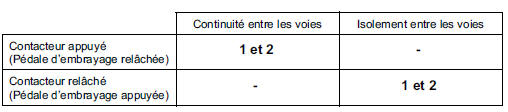
AFTER REPAIR
Carry out a new system diagnosis.
Deal with any other faults.
Erase the stored faults.
| ET042 | CRUISE CONTROL / SPEED LIMITER |
INSTRUCTIONS
State ET032: "Cruise control deactivation" is directly linked to state ET042: "Cruise control / speed limiter".
Cruise control remains disabled until the vehicle exceeds a speed of V 30 km/h.
Nine states are linked. As soon as one of them changes to an active status, the cruise control is immediately disabled.
Special notes: Carry out the checks only if the states are inconsistent with the position of the switches.
ETAT1, ETAT2 missing, on/off switch pressed (ET042 "INACTIVE").
Check the wiring of the cruise control on/off switch and of the computer (32-way black connector). Repair if necessary.- Check and confirm the presence of the ignition-switched + on pin A2 of the cruise control/speed limiter switch connector.
- Remove and test the operation of the cruise control/speed limiter switch:
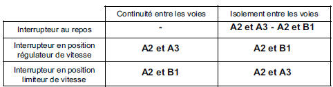
- Check and ensure continuity and absence of parasitic resistance of the link between pin A3 (cruise control) or B1 (speed limiter) of the switch connector and pin A2 (cruise control) or C3 (speed limiter) of the 32-way black ECU connector.
Replace the switch if necessary.
AFTER REPAIR
Carry out a new system diagnosis.
Deal with any other faults.
Erase the stored faults.
ETAT1, ETAT2, switch at rest.
Check the wiring of the cruise control on/off switch and of the computer (32-way black connector). Repair if necessary.- Remove and test the operation of the cruise control/speed limiter switch:
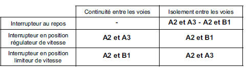
- Replace the brake switch if necessary.
- Check and confirm the 12 V insulation of the wiring between pin A3 (cruise control) or pin B1 (speed limiter) of the cruise control/speed limiter switch connector and pin A2 (cruise control) or pin C3 (speed limiter) of the black 32-pin ECU connector.
AFTER REPAIR
Carry out a new system diagnosis.
Deal with any other faults.
Erase the stored faults.
ETAT3, ETAT4, ETAT5, ETAT6 missing, button pressed (ET042 "INACTIVE").
- Lock the airbag ECU and remove the driver's front airbag (refer to the Technical Notes covering this subject).
- Check the condition and correct connection of the 3-way black connector under the driver's front airbag. Repair if necessary.
- Disconnect the 3-way connector and, on the button side, check the resistance values of the buttons:

If the values are not within specification, replace the steering wheel controls.
If the values are correct, reconnect the black 3-pin connector and carry out the same measurements at the black 32-pin ECU connector between pins D3 and D2.
- If the fault persists, check the wiring: engine injection ECU / steering wheel clock spring, using the appropriate wiring diagram (line resistance, short circuit, etc.).
Carry out the necessary repairs.
- If the values are correct, contact your techline.
AFTER REPAIR
Carry out a new system diagnosis.
Deal with any other faults.
Erase the stored faults.
| ET076 | START |
| ENABLED | When the driver has inserted the start key fob or the key fob has been recognised by the immobiliser system, the cabin central unit enables starting on the injection ECU, state ET076 changes to ENABLED and the vehicle can start. |
| DISABLED | When the driver is no longer recognised by the cabin central unit, it disables starting of the vehicle, state ET076 changes to DISABLED and the vehicle cannot start. Check the key fob battery and carry out a diagnosis of the cabin central unit. |
AFTER REPAIR
Carry out a new system diagnosis.
Deal with any other faults.
Erase the stored faults.
| ET077 | IMPACT DETECTED |
| YES | When the vehicle has been involved in a crash, the injection ECU receives the information sent by the airbag ECU and state ET077 is YES. Switch the ignition off for ten seconds, then switch it back on to allow the engine to start. Then clear the fault codes. |
| NO | When the vehicle has not been involved in any impact, or once the starting procedure described above has been carried out, state ET077 is NO. |
AFTER REPAIR
Carry out a new system diagnosis.
Deal with any other faults.
Erase the stored faults.
| ET078 | AIR CONDITIONING CONTROL |
| OPEN LOOP | When the driver has requested air conditioning control, state ET078 changes to OPEN LOOP. |
| ACTIVE | Using a multimeter, check that there is no switched-off +12 V on pin 1 of the protection and switching unit. Repair if necessary. |
AFTER REPAIR
Carry out a new system diagnosis.
Deal with any other faults.
Erase the stored faults.
| ET079 | AIR CONDITIONING PRESENT |
| YES | If the voltage is absent, check the continuity and the insulation to earth of the following wiring: Pin D1 black connector A, 48-way injection computer → Pin 1 protection and switching unit Repair if necessary. |
| NO | Using a multimeter, check that there is no switched-off +12 V on pin 1 of the protection and switching unit. Repair if necessary. |
AFTER REPAIR
Carry out a new system diagnosis.
Deal with any other faults.
Erase the stored faults.
| ET088 | COMPRESSOR ENGAGEMENT REQUEST |
| ACTIVE | If the voltage is absent, check the continuity and the insulation to earth of the following wiring: Pin D1 black connector A, 48-way injection computer → Pin 1 protection and switching unit Repair if necessary. |
| INACTIVE | Using a multimeter, check that there is no switched-off +12 V on pin 1 of the protection and switching unit. Repair if necessary. |
AFTER REPAIR
Carry out a new system diagnosis.
Deal with any other faults.
Erase the stored faults.
Summary table of parameters
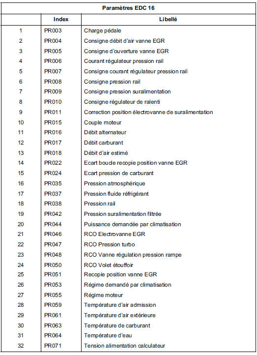
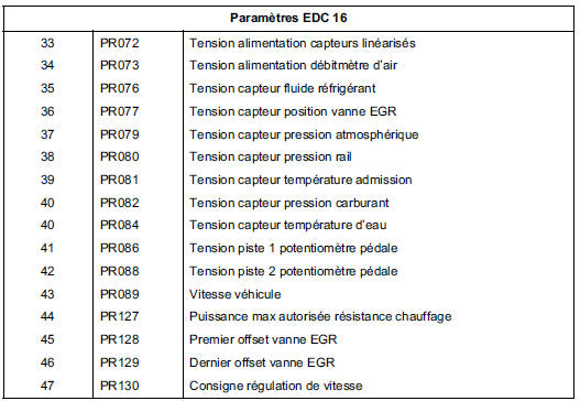
Test yourself
A quick Renault Megane quiz: every answer comes with an explanation and a link to the manual page.