Preliminaries
1. APPLICABILITY OF THIS DOCUMENT
This document describes the diagnosis applicable to all control units with the following characteristics:
| Vehicle(s): Mégane type B and C with F9Q turbocharged engines. Function concerned: BOSCH common rail diesel injection (dCi) |
Control unit name: INJECTION EDC 16 Program no.: 9X VDIAG no.: 44 and 48 |
2. REQUIRED ITEMS FOR DIAGNOSIS To carry out this diagnosis, the following items are essential: Documentation type: Diagnostic methods (this document):
- Assisted diagnosis (built into the diagnostic tool), Repair Manual, software tool: Dialogys.
Wiring diagrams:
- Software tool: Visu Schéma (CD-ROM), paper diagrams.
Diagnostic tool type:
- The diagnostic software tool is CLIP with the Borneo application program.
Use of the NXR is now prohibited for the Mégane.
In addition, the XR25 and Optima 5800 tools are also no longer used.
Essential tool type:
| ESSENTIAL SPECIALIST TOOLING |
| Multimeter |
| Specific interface box Reference Elé. 1674 Electrical fault-finding box Reference Elé. 1681 |
3. REMINDERS
Procedure
To diagnose the vehicle control units, switch the ignition to diagnostic mode (+ after forced ignition).
Proceed as follows:
- Place the vehicle key on the key holder (vehicles without key scenario 1, entry level, without hands-free and scenario 2, high end, with hands-free),
- long press (more than 5 seconds) on the "start" button outside starting conditions,
- connect the diagnostic tool and carry out the required operations.
To cut the + after ignition (+AC), proceed as follows:
- disconnect the diagnostic tool,
- briefly press the "start" button twice (less than 3 seconds each time),
- check that the + after ignition supply is cut by the ECU warning lights going out on the instrument panel.
Faults
Faults are reported as either present or stored (having occurred under certain conditions and since disappeared, or always present but not diagnosed under the current conditions).
The present or stored state of faults must be considered when the diagnostic tool is connected after switching on the + after ignition (without operating any components of the system).
For a fault that is present, follow the procedure given in the Fault interpretation section.
For a stored fault, note the displayed faults and apply the instructions section.
If the fault is confirmed by applying the instruction, the fault is present. Repair the fault.
If the fault is not confirmed, check:
- the electrical circuits corresponding to the fault,
- the connectors of these lines (corrosion, bent pins, etc.)
- the resistance of the component detected as faulty,
- the condition of the wiring (melted or cut insulation, chafing).
Conformity check
The conformity check aims to verify states and parameters that do not show a fault on the diagnostic tool when they are inconsistent. This step therefore allows:
- diagnosing faults with no fault code displayed that may correspond to a customer complaint.
- to check that the system operates correctly and to make sure that the fault will not reappear after repair.
This chapter therefore contains a diagnosis of states and parameters, under the conditions required for their check.
Customer complaints - Fault locating tree
If the diagnostic tool check is correct but the customer complaint is still present, then treat the problem as a "customer symptom" concern.
A summary of the overall procedure is available as a flowchart on the following page.4. DIAGNOSTIC PROCEDURE
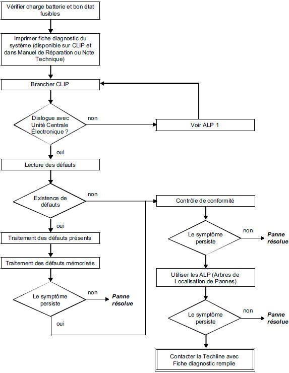
5. DIAGNOSTIC SHEET
WARNING:All faults on a complex system must be diagnosed in full using the appropriate tools. The DIAGNOSTIC SHEET, to be completed during diagnosis, provides and keeps a record of the diagnosis performed. It is an essential part of the dialogue with the manufacturer.
A DIAGNOSTIC SHEET MUST BE COMPLETED EVERY TIME A DIAGNOSIS IS PERFORMED.This sheet will always be required:
- When requesting technical assistance from the techline.
- For approval requests, when replacing parts that require mandatory approval.
- To be attached to the "monitored" parts returned. It is then required for warranty reimbursement and helps with a better analysis of the removed parts.
6. SAFETY INSTRUCTIONS
Any operation on a component requires safety rules to avoid any material damage or personal injury:
- Check that the battery is correctly charged to avoid damage to the ECUs in case of low charge.
- Use the appropriate tools.
7. CLEANLINESS RULES THAT MUST BE STRICTLY OBSERVED DURING WORK ON THE HIGH-PRESSURE DIRECT INJECTION SYSTEM
Risks related to contamination
The system is very sensitive to contamination. The risks caused by introducing contamination are: damage or destruction of the high-pressure injection system and of the engine, seizure or leakage of a component.
All after-sales work must be carried out under very clean conditions. Working under very clean conditions means that no contaminants (particles a few microns in size) have entered the system during disassembly or into the circuits through the fuel fittings.
Cleanliness principles must be applied from the filter through to the injectors.
What contaminates the system?
The contaminating elements are:
- metal or plastic swarf,
- paint,
- fibres:
- from cardboard,
- from brush bristles,
- from paper,
- from clothing,
- cloth fibres.
- foreign bodies such as hair,
- ambient air,
- etc.
IMPORTANT
Before any work on the injection system, make sure the pressure in it is close to 0 bar.
WARNING
Never clean the engine with a high-pressure washer, as this may damage the connectors. In addition, moisture may stagnate in the connectors and cause electrical connection problems.
Precautions to observe before any work on the injection system:
Make sure you have the caps for the fittings to be opened (bag of caps sold at the Spare Parts Store, reference 77 01 206 804). The caps are single-use. After use, the caps must be discarded (once used they are contaminated, and cleaning is not enough to make them reusable). Discard any unused caps.
Make sure you have plastic resealable bags for storing the parts that will be placed in them. The risk of contamination of stored parts is lower. The bags are single-use; once used, they must be discarded.
Make sure you have lint-free cleaning wipes (reference 77 11 211 707). Using ordinary cloth or paper to clean is prohibited, as they shed lint and can contaminate the fuel system circuit. Each wipe may only be used once.
Precautions to observe before opening the fuel circuit
Use new solvent every time you carry out a job (used solvent contains contaminants). Pour it into a container that is free of contaminants.
Use a clean brush in good condition for every operation (the brush must not shed its bristles).
Clean the fittings to be opened using the brush and solvent.
Blow the cleaned areas dry with compressed air (tools, workbench, and parts, fittings and injection system area). Check that no brush bristles remain.
Wash your hands before and during the operation if necessary.
When wearing protective gloves, cover leather gloves with latex gloves.
Precautions to observe during the job
As soon as the circuit is opened, you must plug all openings through which contamination could enter. The plugs to be used are available from the Spare Parts Store. They must never be reused.
Reseal the bag airtight, even if it must be reopened shortly afterwards. Ambient air is a source of contamination.
Any injection system component that has been removed must, after being plugged, be stored in a sealed plastic bag.
Once the circuit has been opened, the use of brushes, thinner, air blow guns, swabs or standard rags is strictly prohibited, as these items may introduce contaminants into the system.
When replacing a component, only remove it from its packaging when fitting it to the vehicle.
8. GENERAL REMARKS
Switching the vehicle on (ignition on)
To diagnose the vehicle control modules, proceed as follows:
- Place the vehicle badge on the badge holder (keyless vehicle scenarios 1 (entry level, non hands-free) and 2 (top of range, hands-free))
- Press and hold the "start" button (more than 5 seconds) when starting conditions are not met
- Then connect the diagnostic tool and carry out the required operations
Test yourself
A quick Renault Megane quiz: every answer comes with an explanation and a link to the manual page.