Engine and peripherals
Engine and gearbox assembly
In this manual: Engine and peripherals
~7min read
Essential special tools |
|
| Mot. 1202-01 | Spring clamp pliers (large model) |
| Mot. 1202-02 | Spring clamp pliers (small model) |
| Mot. 1448 | Remote spring clamp pliers |
Essential equipment |
| safety straps |
| charging station |
| load positioner |
Tightening torques |
|
| Lower ball joint nut | 6.2 daN.m |
| Driveshaft nut | 28 daN.m |
| Steering ball joint nut | 3.7 daN.m |
| Upper pendulum suspension link bolt | 10.5 daN.m |
| Upper front end panel bolt | 2.1 daN.m |
| Lower front end panel bolt | 4.4 daN.m |
| Pendulum suspension cover bolt on engine | 6.2 daN.m |
| Torque reaction rod bolt (on subframe) | 10.5 daN.m |
| Torque reaction rod bolt (on F engines) | 18 daN.m |
| Torque reaction rod bolt (on K engines) | 10.5 daN.m |
| Wheel bolt | 11 daN.m |
| Front radiator crossmember bolt | 10.5 daN.m |
| Rear crossmember bolt | 2.1 daN.m |

REMOVAL
- Position the vehicle on a two-post lift.
- Disconnect the battery.
- Remove:
- the engine covers,
- the front wheels,
- the engine undershield,
- the right and left mudguards.
- Drain:
- the refrigerant circuit using a charging station,
- the cooling circuit at the lower radiator hose using tools (Mot. 1202-01), (Mot. 1202-02) and (Mot. 1448),
- the gearbox if necessary,
- the engine if necessary.
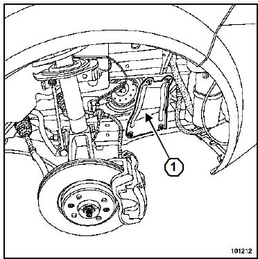
- Remove:
- the side reinforcements of the radiator crossmember (1),
- the bumper mountings,
- the bumper cover
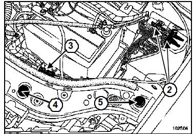
- Disconnect the two connectors (2).
- Unclip the bonnet release cable (3).
- Remove:
- the clip (4),
- the mounting (5).
- Disconnect the windscreen washer pipes.
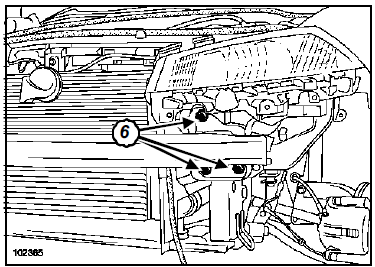
- Remove:
- the front end panel mounting bolts (6),
- the front end panel.
K4J
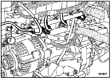
- Disconnect the fuel supply fitting (7).
F4R or K4M
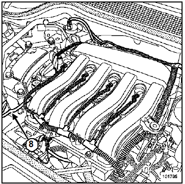
- Disconnect the fuel supply hose (8) from the injection rail.
F9Q or K9K
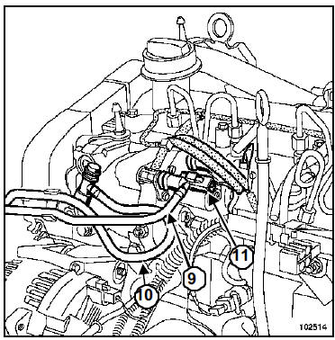
- Strictly observe the cleanliness precautions (Diesel Injection chapter, Diesel Injection Safety, page 13B-9).
- Be aware of the amount of diesel and the residual pressure in the lines.
- Remove:
- the fuel supply hose (9),
- the fuel return hose (10).
- Disconnect the electrical connector (11).
- Fit plugs to the openings.
- Disconnect the connector from the cooling fan assembly.
- Disconnect the upper radiator hose using tool (Mot. 1202-01) or (Mot. 1202-02) or (Mot. 448).
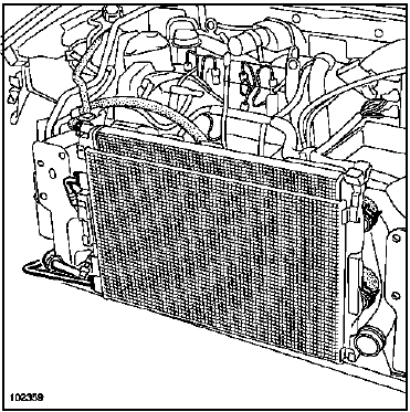
- Disconnect the two hoses from the radiator expansion tank.
- Remove:
- the two A/C lines from the condenser,
- the cooling assembly,
- the A/C line between the A/C compressor and the receiver-drier.
K4J
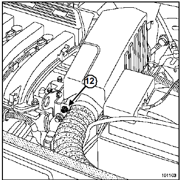
- Remove the bracket (12) from the air resonator.
- Remove:
- the air resonator,
- the battery.
F4R or F9Q or K4M or K9K
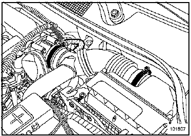
- Remove the air filter outlet duct.
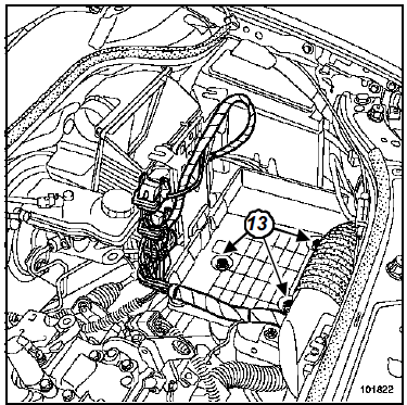
- Remove the battery tray mounting bolts (13).
- Disconnect the control unit connectors.
- Remove:
- the battery tray,
- the control unit bracket.
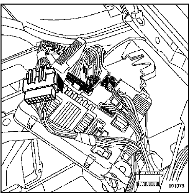
- Disconnect:
- the relay box harness connectors,
- the earth strap from the body.
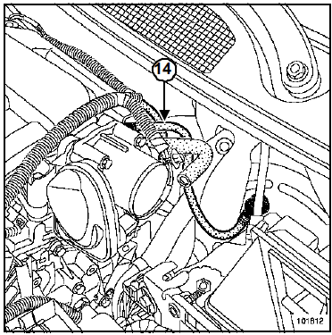
- Remove the brake booster hose (14).
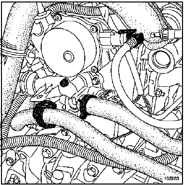
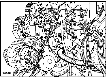
- Disconnect the heater matrix hoses from the coolant housing using tools (Mot. 1202-01), (Mot. 1202-02) and (Mot. 1448).
- Disconnect the oxygen sensors.
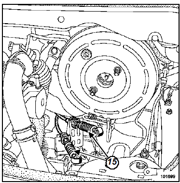
- Remove the gearbox controls (15).
CAUTION Do not touch the gearbox selector spool.
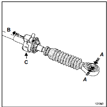
- Release the two cables from the gearbox levers:
- pinch the gearbox control at (A),
- pull out the pin at (B),
- lift the gearbox control at (C).
DP0
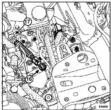
- Remove:
- the ball joint (16) of the multifunction switch cable,
- the wiring (17) of the multifunction switch cable by releasing the cable sheath stop.
K4J or K4M or K9K
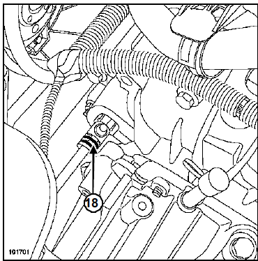
- Remove the hydraulic clutch control (18).
F4R or F9Q
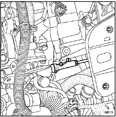
- Press the clip.
- Disconnect the supply line.
- Remove the hydraulic clutch control from the bulkhead.
Note: Plug the line to prevent fluid from escaping.
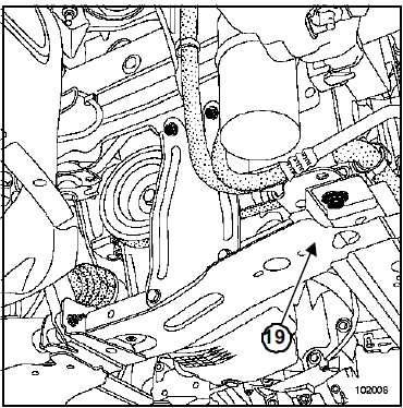
- Remove:
- the driveshafts (Transmission chapter),
- the exhaust downpipe mountings,
- the lower torque reaction rod,
- the upper torque reaction rod (F9Q and F4R engines only),
- the lower radiator crossmember (19).
- Fit the workshop crane fitted with a load positioner or a chain.
IMPORTANT The chain must be at least 90 cm long.
K4J or K4M or K9K
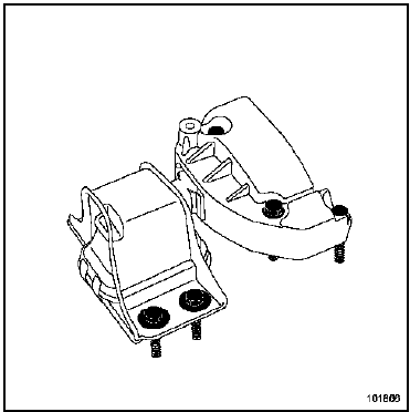
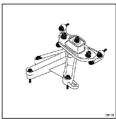
- Remove:
- the engine pendulum mount,
- the gearbox pendulum mount,
- the "engine - gearbox" assembly.
F4R or F9Q
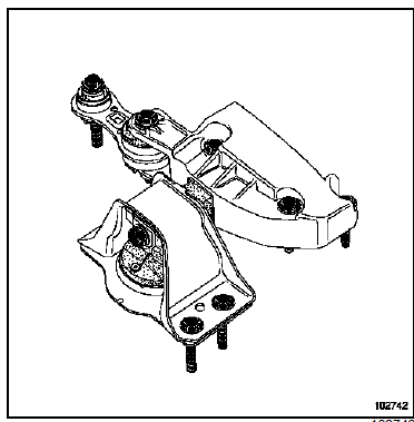
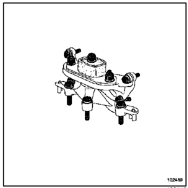
- Remove:
- the engine pendulum mount,
- the gearbox pendulum mount,
- the "engine - gearbox" assembly.
INSTALLATION
- Position the "engine - gearbox" assembly in the vehicle.
- Refit:
- the engine pendulum mount (Engine Mounting chapter, Setting Values - pendulum mount, page 19D-1),
- the gearbox pendulum mount (Engine Mounting chapter, Setting Values - pendulum mount, page 19D-1),
- the lower torque reaction rod (Engine Mounting chapter).
F4R or F9Q
- the upper torque reaction rod (Engine Mounting chapter).
- Refit in the reverse order of removal.
- Tighten to the following torques:
- the lower ball joint nut (6.2 daN.m),
- the driveshaft nut (28 daN.m),
- the steering ball joint nut (3.7 daN.m),
- the upper pendulum mount bracket bolt (10.5 daN.m),
- the upper front end mounting bolt (2.1 daN.m),
- the lower front end mounting bolt (4.4 daN.m),
- the pendulum mount cover bolt to engine (6.2 daN.m),
- the torque reaction rod bolt (to subframe) (10.5 daN.m),
- the torque reaction rod bolt (on F engines) (18 daN.m),
- the torque reaction rod bolt (on K engines) (10.5 daN.m),
- the wheel bolt (11 daN.m),
- the front radiator crossmember bolt (10.5 daN.m),
- the rear crossmember bolt (2.1 daN.m).
- Add brake fluid to the brake fluid reservoir.
Carry out:
- the clutch bleeding (Mechanical Controls chapter),
- topping up the gearbox oil if necessary,
- topping up the engine oil if necessary,
- filling and bleeding the coolant (Cooling chapter),
- recharging the refrigerant circuit using a recharging station.
- Press the brake pedal several times to bring the pistons, pads and brake discs into contact.
- Correctly secure the brake hose and the anti-lock braking system wheel sensor wiring.
Connect the battery; carry out the necessary re-learns (see Electrical Equipment chapter).
Note: Be sure to initialise the xenon lighting system (if the vehicle is so equipped; see Xenon lamps chapter).Test yourself
A quick Renault Megane quiz: every answer comes with an explanation and a link to the manual page.
Was this page helpful?