Check Mode Procedure. Data List / Active Test. Definition Of Terms
Check Mode Procedure
CHECK MODE PROCEDURE
DESCRIPTION
(a) Check mode has a higher sensitivity to malfunctions and can detect malfunctions that normal mode cannot detect. Check mode can also detect all of the malfunctions that normal mode can detect. In check mode, DTCs are detected with 1 trip detection logic.
CHECK MODE PROCEDURE
(a) Make sure that the following conditions are met:
- The battery voltage is 11 V or more.
- The throttle valve is fully closed.
- The shift lever is in P or N.
- The air conditioning is off.
(b) Connect the Techstream to the DLC3.
(c) Turn the engine switch on (IG).
(d) Turn the Techstream on.
(e) Enter the following menus: Powertrain / Transmission / Utility / Check Mode.
Powertrain > Transmission > UtilityCheck Mode
(f) Change the ECM to check mode and check that the MIL flashes as shown in the illustration.
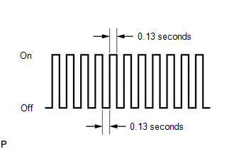
NOTICE:
All DTCs and freeze frame data will be cleared if: 1) the Techstream is used to change the ECM from normal mode to check mode or vice versa; or 2) during check mode, the engine switch is turned from on (IG) to off.
Before entering check mode, make a note of the DTCs and freeze frame data.
(g) Start the engine. The MIL should turn off after the engine starts.
(h) Perform Monitor Drive Pattern for the ECT.
Click here 
(Or, simulate the conditions of the malfunction described by the customer.)
(i) After simulating the malfunction conditions, use the Techstream to check for DTCs and freeze frame data.
Data List / Active Test
DATA LIST / ACTIVE TEST
DATA LIST
NOTICE:
In the table below, the values listed under "Normal Condition" are reference values. Do not depend solely on these reference values when deciding whether a part is faulty or not.
HINT:
Using the Techstream to read the Data List allows the values or states of switches, sensors, actuators and other items to be read without removing any parts. This non-intrusive inspection can be very useful because intermittent conditions or signals may be discovered before parts or wiring is disturbed. Reading the Data List information early in troubleshooting is one way to save diagnostic time.
(a) Warm up the engine.
(b) Turn the engine switch off.
(c) Connect the Techstream to the DLC3.
(d) Turn the engine switch on (IG).
(e) Turn the Techstream on.
(f) Enter the following menus: Powertrain / Transmission / Data List.
(g) Read the Data List according to the display on the Techstream.
Powertrain > Transmission > Data ListTester Display | Measurement Item | Range | Normal Condition | Diagnostic Note |
|---|---|---|---|---|
Total Distance Traveled |
Total distance traveled |
Min.: 0 Max.: 16777215 |
- |
- |
Total Distance Traveled - Unit |
Unit for Total Distance Traveled |
km or mile |
- |
- |
Vehicle Speed |
Vehicle speed |
Min.: 0 km/h Max.: 255 km/h |
Actual vehicle speed |
|
Engine Speed |
Engine Speed |
Min.: 0 rpm Max.: 16383 rpm |
600 to 700 rpm: Engine idling (shift lever in N, engine warmed up and A/C off) |
When the crankshaft position sensor is malfunctioning, "Engine Speed" is approximately 0 rpm or varies greatly from the actual engine speed. |
Calculate Load |
Load calculated by ECM |
Min.: 0% Max.: 100% |
- |
|
Coolant Temperature |
Engine coolant temperature |
Min.: -40°C (-40°F) Max.: 140 °C |
75 to 100 °C: After warming up |
This is the engine coolant temperature. HINT:
|
Intake Air Temperature |
Intake air temperature |
Min.: -40°C (-40°F) Max.: 140 °C |
Equivalent to temperature at location of mass air flow meter sub-assembly |
|
Ambient Temperature |
Ambient temperature |
Min.: -40°C (-40°F) Max.: 215 °C |
Equivalent to ambient temperature |
This is the ambient temperature. HINT: After a long soak, the engine coolant temperature, intake air temperature and ambient air temperature will be approximately equal. |
Engine Run Time |
Engine run time |
Min.: 0 seconds Max.: 65535 seconds |
Time after engine start |
- |
Battery Voltage |
Battery voltage |
Min.: 0 Max.: 65.5 V |
11 to 14 V: Engine switch on (IG) |
If 11 V or less, characteristics of some electrical components may change. |
BATT Voltage |
Battery voltage |
Min.: 0 Max.: 79.998 V |
11 to 14 V: Engine switch on (IG) |
- |
Glow Indicator Supported |
Glow indicator supported |
Unsupp or Supp |
- |
- |
Throttle Position Sensor No.1 Voltage % |
Absolute No. 1 throttle position sensor |
Min.: 0% Max.: 100% |
|
The No. 1 throttle position sensor output is converted using 5 V = 100%. HINT: If there are no throttle position sensor DTCs stored, it is possible to conclude that the throttle position sensor system is normal. |
Starter SW |
Starter signal |
ON or OFF |
|
- |
Neutral Position SW |
Park/neutral position switch status |
ON or OFF |
|
When the shift lever position displayed on the Techstream differs from the actual position, the adjustment of the park/neutral position switch assembly or shift cable may be incorrect. HINT: If a malfunction still occurs even after adjusting these parts, refer to DTC P070513 or P070562*3. |
Stop Light SW |
Stop light switch status |
ON or OFF |
|
- |
Cruise Main SW |
Cruise control main switch status |
ON or OFF |
|
- |
Complete Parts Monitor |
Comprehensive component monitor |
Not Avl or Avail |
- |
|
Fuel System Monitor |
Fuel system monitor |
Not Avl or Avail |
- |
|
Fuel System Monitor Result |
Fuel system monitor |
Compl or Incmpl |
- |
|
Misfire Monitor |
Misfire monitor |
Not Avl or Avail |
- |
|
EGR/VVT Monitor |
EGR/VVT monitor |
Not Avl or Avail |
- |
|
EGR/VVT Monitor Result |
EGR/VVT monitor |
Compl or Incmpl |
- |
|
A/F (O2) Sensor Heater Monitor |
O2S (A/FS) heater monitor |
Not Avl or Avail |
- |
|
A/F (O2) Sensor Heater Monitor Result |
O2S (A/FS) heater monitor |
Compl or Incmpl |
- |
|
A/F (O2) Sensor Monitor |
O2S (A/FS) monitor |
Not Avl or Avail |
- |
|
A/F (O2) Sensor Monitor Result |
O2S (A/FS) monitor |
Compl or Incmpl |
- |
|
Secondary Air Injection System Monitor |
Secondary air injection system monitor |
Not Avl or Avail |
- |
|
Secondary Air Injection System Monitor Result |
Secondary air injection system monitor |
Compl or Incmpl |
- |
|
EVAP Monitor |
EVAP monitor |
Not Avl or Avail |
- |
|
EVAP Monitor Result |
EVAP monitor |
Compl or Incmpl |
- |
|
Heated Catalyst Monitor |
Heated catalyst monitor |
Not Avl or Avail |
- |
|
Heated Catalyst Monitor Result |
Heated catalyst monitor |
Compl or Incmpl |
- |
|
Catalyst Monitor |
Catalyst monitor |
Not Avl or Avail |
- |
|
Catalyst Monitor Result |
Catalyst monitor |
Compl or Incmpl |
- |
|
Component Monitor ENA (Current) |
Comprehensive component monitor |
Unable or Enable |
- |
|
Component Monitor Result (Current) |
Comprehensive component monitor |
Compl or Incmpl |
- |
|
Fuel System Monitor ENA (Current) |
Fuel system monitor |
Unable or Enable |
- |
|
Fuel System Monitor Result (Current) |
Fuel system monitor |
Compl or Incmpl |
- |
|
Misfire Monitor ENA (Current) |
Misfire monitor |
Unable or Enable |
- |
|
Misfire Monitor Result (Current) |
Misfire monitor |
Compl or Incmpl |
- |
|
EGR/VVT Monitor ENA (Current) |
EGR monitor |
Unable or Enable |
- |
|
EGR/VVT Monitor Result (Current) |
EGR monitor |
Compl or Incmpl |
- |
|
O2 Sensor Heater ENA (Current) |
O2S (A/FS) heater monitor |
Unable or Enable |
- |
|
O2 Sensor Heater Monitor Result (Current) |
O2S (A/FS) heater monitor |
Compl or Incmpl |
- |
|
A/F (O2) Sensor Monitor ENA (Current) |
O2S (A/FS) monitor |
Unable or Enable |
- |
|
A/F (O2) Sensor Monitor Result (Current) |
O2S (A/FS) monitor |
Compl or Incmpl |
- |
|
Secondary Air Injection System Monitor ENA (Current) |
Secondary air injection system monitor |
Unable or Enable |
- |
|
Secondary Air Injection System Monitor Result (Current) |
Secondary air injection system monitor |
Compl or Incmpl |
- |
|
EVAP Monitor ENA (Current) |
EVAP monitor |
Unable or Enable |
- |
|
EVAP Monitor Result (Current) |
EVAP monitor |
Compl or Incmpl |
- |
|
Heated Catalyst Monitor ENA (Current) |
Heated catalyst monitor |
Unable or Enable |
- |
|
Heated Catalyst Monitor Result (Current) |
Heated catalyst monitor |
Compl or Incmpl |
- |
|
Catalyst Monitor ENA (Current) |
Catalyst monitor |
Unable or Enable |
- |
|
Catalyst Monitor Result (Current) |
Catalyst monitor |
Compl or Incmpl |
- |
|
TC Terminal |
TC terminal Status |
ON or OFF |
- |
- |
MIL |
MIL status |
ON or OFF |
ON: MIL ON |
- |
MIL ON Run Distance |
MIL ON run distance |
Min.: 0 km (0 mile) Max.: 65535 km (40723 mile) |
Distance driven since DTC detected |
- |
Running Time from MIL ON |
Running time from MIL ON |
Min.: 0 min Max.: 65535 min |
Equivalent to running time since MIL illuminated |
- |
Time after DTC Cleared |
Time after DTC cleared |
Min.: 0 min Max.: 65535 min |
Equivalent to time since DTCs cleared |
- |
Distance from DTC Cleared |
Distance after DTC cleared |
Min.: 0 km (0 mile) Max.: 65535 km (40723 mile) |
Equivalent to time since DTCs cleared |
- |
Warmup Cycle Cleared DTC |
Warm-up cycle after DTC cleared |
Min.: 0 Max.: 255 |
Number of warm-up cycles since DTCs cleared |
- |
OBD Requirements |
OBD requirement |
- |
OBD II (California ARB) |
- |
Number of Emission DTC |
Emission related DTCs |
Min.: 0 Max.: 127 |
- |
- |
Accel Position from EFI |
Absolute Accelerator Pedal Position |
Min.: 0.0% Max.: 127.5% |
- |
- |
NT Sensor Speed |
Input shaft speed |
Min.: 0 rpm Max.: 12750 rpm |
|
Data is displayed in increments of 50 rpm |
NC Sensor Speed |
Counter gear speed |
Min.: 0 rpm Max.: 12750 rpm |
- |
- |
Shift SW Status (P Range) |
Park/neutral position switch status |
ON or OFF |
|
When the shift lever position displayed on the Techstream differs from the actual position, the adjustment of the park/neutral position switch assembly or shift cable may be incorrect. HINT: If a malfunction still occurs even after adjusting these parts, refer to DTC P070513 or P070562*3. |
Shift SW Status (R Range) |
Park/neutral position switch status |
ON or OFF |
|
When the shift lever position displayed on the Techstream differs from the actual position, the adjustment of the park/neutral position switch assembly or shift cable may be incorrect. HINT: If a malfunction still occurs even after adjusting these parts, refer to DTC P070513 or P070562*3. |
Shift SW Status (N Range) |
Park/neutral position switch status |
ON or OFF |
|
When the shift lever position displayed on the Techstream differs from the actual position, the adjustment of the park/neutral position switch assembly or shift cable may be incorrect. HINT: If a malfunction still occurs even after adjusting these parts, refer to DTC P070513 or P070562*3. |
Shift SW Status (N,P Range) |
Park/neutral position switch status |
ON or OFF |
|
When the shift lever position displayed on the Techstream differs from the actual position, the adjustment of the park/neutral position switch assembly or shift cable may be incorrect. HINT: If a malfunction still occurs even after adjusting these parts, refer to DTC P070513 or P070562*3. |
Shift SW Status (N,P Range) Supported |
Status of park/neutral position switch (N or P) supported |
Unsupp or Supp |
Supp |
- |
Shift SW Status (S Range) |
Sport (S) mode select switch status |
ON or OFF |
|
- |
Shift SW Status (D Range) |
Park/neutral position switch status |
ON or OFF |
|
When the shift lever position displayed on the Techstream differs from the actual position, the adjustment of the park/neutral position switch assembly or shift cable may be incorrect. HINT: If a malfunction still occurs even after adjusting these parts, refer to DTC P070513 or P070562*3. |
A/T Oil Temperature No.1 |
ATF temperature sensor value |
Min.: -40°C (-40°F) Max.: 150 °C |
|
If value is -40°C (-40°F) or 150 °C, ATF temperature sensor circuit is open or shorted |
ATF Thermal Degradation Estimate |
Estimated value of ATF thermal degradation |
Min.: 0 Max.: 65535 |
- |
If 50000 or more is displayed, thermal degradation of the ATF is suspected. Perform ATF Thermal Degradation Estimate Reset after replacing the ATF. |
NT Sensor Voltage |
NT sensor voltage |
Min.: 0.000 V Max.: 4.999 V |
0.1 to 1.9 V: Engine idling |
- |
NC Sensor Voltage |
NC sensor voltage |
Min.: 0.000 V Max.: 4.999 V |
0.1 to 1.9 V: Engine idling |
- |
Lock Up Status |
Lock up |
ON or OFF |
|
- |
Shift Status |
ECM gear shift command |
1st, 2nd, 3rd, 4th, 5th, 6th, 7th or 8th |
Same as actual gear |
- |
Solenoid (SLT) |
Solenoid (SLT) valve status |
ON or OFF |
|
- |
Solenoid (SLU) |
Solenoid (SLU) valve status |
ON or OFF |
|
- |
Solenoid (SL1) |
Solenoid (SL1) valve status |
ON or OFF |
|
The value of this item only changes when performing an Active Test. |
Solenoid (SL2) |
Solenoid (SL2) valve status |
ON or OFF |
|
The value of this item only changes when performing an Active Test. |
Solenoid (SL3) |
Solenoid (SL3) valve status |
ON or OFF |
|
The value of this item only changes when performing an Active Test. |
Solenoid (SL4) |
Solenoid (SL4) valve status |
ON or OFF |
|
The value of this item only changes when performing an Active Test. |
Solenoid (SL5) |
Solenoid (SL5) valve status |
ON or OFF |
|
The value of this item only changes when performing an Active Test. |
Solenoid (SL6) |
Solenoid (SL6) valve status |
ON or OFF |
|
The value of this item only changes when performing an Active Test. |
Solenoid (SL) |
Solenoid (SL) valve status |
ON or OFF |
|
- |
HINT:
- *1:
- Avail: The monitor is available on the vehicle.
- Not Avl: The monitor is not available on the vehicle.
- Incmpl / Compl: The item changes from Incmpl to Compl if the monitor was completed at least once at some time in the past. This item does not change when the engine switch is turned off. However, the item changes back to Incmpl when DTCs are cleared or cable is disconnected from the negative (-) battery terminal.
- Monitor result (mode 06): The last judgment result is output. This is not cleared when the engine switch is turned off, but is cleared when DTCs are cleared.
- *2:
- Enable: The monitor is available on the vehicle.
- Unable: The monitor is not available on the vehicle.
- Incmpl / Compl: The item changes from Incmpl to Compl if the monitor was completed during the current trip. The item changes back to Incmpl when the engine switch is turned off.
- Monitor result (mode 06): The last judgment result is output. This is not cleared when the engine switch is turned off, but is cleared when DTCs are cleared. Therefore, only when DTCs are cleared at the beginning of a trip does the system monitor (Test Result [Monitor Status]) and monitor result (mode 06) match.
- *3: Refer to DTC P070513 or P070562.
Click here

(h) Enter the following menus: Powertrain / Engine / Data List.
(i) Read the Data List according to the display on the Techstream.
Powertrain > Engine > Data ListTester Display | Measurement Item | Range | Normal Condition | Diagnostic Note |
|---|---|---|---|---|
Sport Shift Up SW |
Sport shift up switch status |
ON or OFF |
|
- |
Sport Shift Down SW |
Sport shift down switch status |
ON or OFF |
|
- |
Shift SW Status (S Range) |
Sport (S) mode select switch status |
ON or OFF |
|
- |
ACTIVE TEST
HINT:
Using the Techstream to perform Active Tests allows relays, VSVs, actuators and other items to be operated without removing any parts. This non-intrusive functional inspection can be very useful because intermittent operation may be discovered before parts or wiring is disturbed. Performing Active Tests early in troubleshooting is one way to save diagnostic time. Data List information can be displayed while performing Active Tests.
(a) Warm up the engine.
(b) Turn the engine switch off.
(c) Connect the Techstream to the DLC3.
(d) Turn the engine switch on (IG).
(e) Turn the Techstream on.
(f) Enter the following menus: Powertrain / Transmission / Active Test.
(g) Perform the Active Test according to the display on the Techstream.
Powertrain > Transmission > Active TestTester Display | Measurement Item | Control Range | Diagnostic Note |
|---|---|---|---|
Activate the TC Terminal |
Connects and disconnects terminals TC and TE1 (For activation of fluid temperature detection mode) |
ON or OFF |
[Vehicle Condition]
|
Control the Shift Position |
Operates the solenoid valves to allow gears to be selected manually |
1st/2nd/3rd/4th/5th/6th/7th/8th Start/Stop |
Can be used to check operation of the solenoid valves. [Vehicle Condition] Vehicle speed: 50 km/h or less |
Activate the Solenoid (SLU) |
Operates the solenoid (SLU) valve |
ON or OFF |
[Vehicle Condition]
|
Activate the Solenoid (SLT) |
Operates the solenoid (SLT) valve to raise the line pressure |
ON or OFF HINT:
|
[Vehicle Condition] Engine running |
Activate the Lock Up Solenoid |
Operates the solenoid (SLU and SL) valve to control the automatic transaxle lock-up condition |
ON or OFF |
Can be used to check the operation of the solenoid (SLU and SL) valve. [Vehicle Condition] Vehicle speed: 60 km/h or more |
Activate the Solenoid (SL) |
Operates the solenoid (SL) valve |
ON or OFF |
[Vehicle Condition]
|
Activate the Solenoid (SL1) |
Operates the solenoid (SL1) valve |
ON or OFF |
[Vehicle Condition]
|
Activate the Solenoid (SL2) |
Operates the solenoid (SL2) valve |
ON or OFF |
[Vehicle Condition]
|
Activate the Solenoid (SL3) |
Operates the solenoid (SL3) valve |
ON or OFF |
[Vehicle Condition]
|
Activate the Solenoid (SL4) |
Operates the solenoid (SL4) valve |
ON or OFF |
[Vehicle Condition]
|
Activate the Solenoid (SL5) |
Operates the solenoid (SL5) valve |
ON or OFF |
[Vehicle Condition]
|
Activate the Solenoid (SL6) |
Operates the solenoid (SL6) valve |
ON or OFF |
[Vehicle Condition]
|
HINT:
- Performing the Active Test "Activate the Solenoid (SLT)" allows the change in line pressure to be checked with SST installed to the automatic transaxle. The same SST is used for the Hydraulic Test.
Click here
- Note that the pressure readings for the Active Test and Hydraulic Test are different.
Definition Of Terms
DEFINITION OF TERMS
Term | Definition |
|---|---|
Monitor description |
Description of what the ECM monitors and how it detects malfunctions (monitoring purpose and details). |
Related DTCs |
Group of diagnostic trouble codes that are output by the ECM based on the same malfunction detection logic. |
Typical enabling condition |
Preconditions that allow the ECM to detect malfunctions. With all preconditions satisfied, the ECM stores a DTC when the monitored value(s) exceeds the malfunction threshold(s). |
Sequence of operation |
The priority order that is applied to monitoring if multiple sensors and components are used to detect the malfunction. While one sensor is being monitored, the next sensor or component will not be monitored. |
Required sensor/Components |
The sensors and components that are used by the ECM to detect malfunctions. |
Frequency of operation |
The number of times that the ECM checks for malfunctions per driving cycle. "Once per driving cycle" means that the ECM detects a malfunction only once during a single driving cycle. "Continuous" means that the ECM detects a malfunction every time the enabling conditions are met. |
Duration |
The minimum time for which the ECM must detect a continuous deviation in the monitored value(s) in order to store a DTC. Timing begins after the "typical enabling conditions" are met. |
Typical malfunction thresholds |
Value beyond which the ECM will determine that there is a malfunction and stores a DTC. |
MIL operation |
MIL illumination timing after a malfunction is detected. "Immediate" means that the ECM illuminates the MIL the instant the ECM determines that there is a malfunction. "2 driving cycles" means that the ECM illuminates the MIL if the same malfunction is detected again in the next driving cycle. |
Component operating range |
Normal operation range of sensors and solenoids under normal driving conditions. Use these ranges as a reference. The ranges cannot be used to judge if a sensor or solenoid is defective or not. |