Oil Cooler
Components
COMPONENTS
ILLUSTRATION
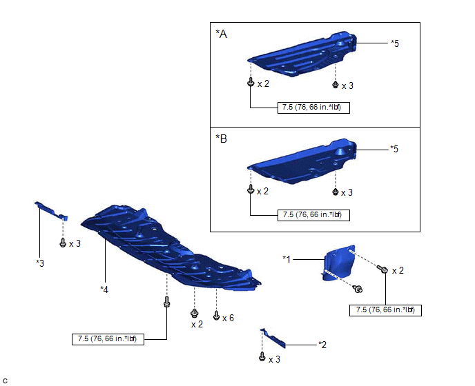
*A |
Type A |
*B |
Type B |
*1 |
FRONT FENDER APRON SEAL LH |
*2 |
FRONT WHEEL OPENING EXTENSION PAD LH |
*3 |
FRONT WHEEL OPENING EXTENSION PAD RH |
*4 |
NO. 1 ENGINE UNDER COVER |
*5 |
REAR ENGINE UNDER COVER LH |
- |
- |
 |
N*m (kgf*cm, ft.*lbf): Specified torque |
- |
- |
ILLUSTRATION
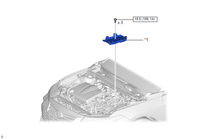
*1 |
BATTERY CLAMP SUB-ASSEMBLY |
- |
- |
|
N*m (kgf*cm, ft.*lbf): Specified torque |
- |
- |
ILLUSTRATION
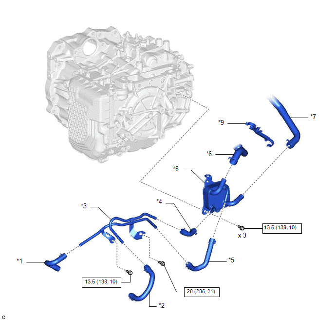
*1 |
OUTLET NO. 1 OIL COOLER HOSE |
*2 |
INLET NO. 1 OIL COOLER HOSE |
*3 |
NO. 1 OIL COOLER TUBE SUB-ASSEMBLY WITHOUT HOSE |
*4 |
INLET NO. 2 OIL COOLER HOSE |
*5 |
OUTLET NO. 2 OIL COOLER HOSE |
*6 |
NO. 1 WATER BY-PASS HOSE |
*7 |
WATER BY-PASS HOSE ASSEMBLY |
*8 |
TRANSMISSION OIL COOLER |
*9 |
TRANSMISSION BREATHER CLAMP |
- |
- |
|
N*m (kgf*cm, ft.*lbf): Specified torque |
- |
- |
Installation
INSTALLATION
PROCEDURE
1. INSTALL TRANSMISSION OIL COOLER
(a) Engage the hook and temporarily install the transmission oil cooler to the automatic transaxle case sub-assembly with the bolt (A). |
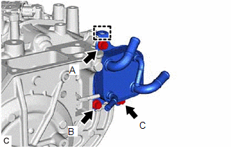 |
(b) Install the bolt (B).
Torque:
13,5 N·m {138 kgf·cm, 10 ft·lbf}
(c) Install the bolt (C).
Torque:
13,5 N·m {138 kgf·cm, 10 ft·lbf}
(d) Fully tighten the bolt (A) to install the transmission oil cooler.
Torque:
13,5 N·m {138 kgf·cm, 10 ft·lbf}
2. CONNECT WATER BY-PASS HOSE ASSEMBLY
(a) Connect the water by-pass hose assembly to the transmission oil cooler and slide the clip to secure it.
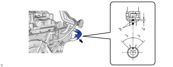
*a |
2 to 7 mm (0.0787 to 0.276 in.) |
*b |
Paint Mark |
*c |
45° (Claw of Clip Location) |
- |
- |
NOTICE:
- Make sure to slide the water by-pass hose assembly until it contacts the hose stopper of the transmission oil cooler.
- Make sure to align the paint mark of the water by-pass hose assembly with the paint mark of the transmission oil cooler.
- Make sure that the claws of the clip are within the location shown in the illustration.
3. CONNECT NO. 1 WATER BY-PASS HOSE
(a) Connect the No. 1 water by-pass hose to the transmission oil cooler and slide the clip to secure it.
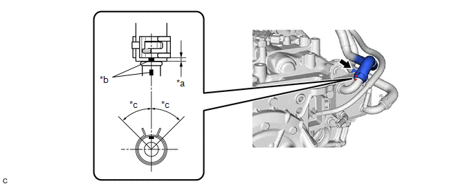
*a |
2 to 7 mm (0.0787 to 0.276 in.) |
*b |
Paint Mark |
*c |
45° (Claw of Clip Location) |
- |
- |
NOTICE:
- Make sure to slide the No. 1 water by-pass hose until it contacts the hose stopper of the transmission oil cooler.
- Make sure to align the paint mark of the No. 1 water by-pass hose with the paint mark of the transmission oil cooler.
- Make sure that the claws of the clip are within the location shown in the illustration.
(b) Engage the 3 clamps to install the transmission breather clamp.
4. INSTALL NO. 1 OIL COOLER TUBE SUB-ASSEMBLY WITHOUT HOSE
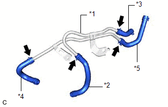
(a) Install the inlet No. 1 oil cooler hose, inlet No. 2 oil cooler hose, outlet No. 1 oil cooler hose and outlet No. 2 oil cooler hose to the No. 1 oil cooler tube sub-assembly without hose and slide the 4 clips to secure them.
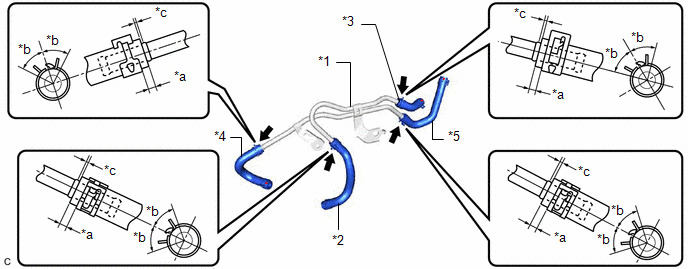
*1 |
No. 1 Oil Cooler Tube Sub-assembly without Hose |
*2 |
Inlet No. 1 Oil Cooler Hose |
*3 |
Inlet No. 2 Oil Cooler Hose |
*4 |
Outlet No. 1 Oil Cooler Hose |
*5 |
Outlet No. 2 Oil Cooler Hose |
- |
- |
*a |
2 to 7 mm (0.0787 to 0.276 in.) |
*b |
45° (Claw of Clip Location) |
*c |
0 to 3 mm (0 to 0.118 in.) |
- |
- |
NOTICE:
- Make sure to slide the inlet No. 1 oil cooler hose, inlet No. 2 oil cooler hose, outlet No. 1 oil cooler hose and outlet No. 2 oil cooler hose until each contacts the hose stopper of the No. 1 oil cooler tube sub-assembly without hose.
- Make sure that the claws of each clip are within the location shown in the illustration.
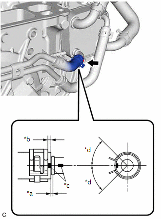
(b) Connect the outlet No. 2 oil cooler hose to the transmission oil cooler and slide the clip to secure it. NOTICE:
|
|
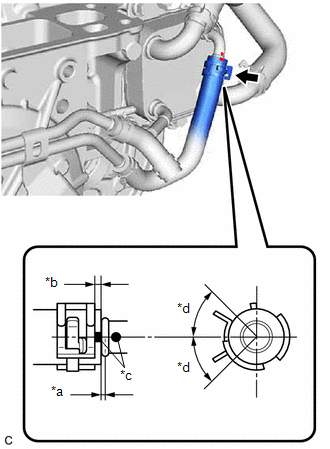
(c) Connect the inlet No. 2 oil cooler hose to the transmission oil cooler and slide the clip to secure it. NOTICE:
|
|
(d) Temporarily install the No. 1 oil cooler tube sub-assembly without hose to the automatic transaxle case sub-assembly with the 2 bolts. |
|
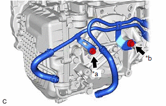
(e) Tighten the 2 bolts.
Torque:
Bolt (A) :
13,5 N·m {138 kgf·cm, 10 ft·lbf}
Bolt (B) :
28 N·m {286 kgf·cm, 21 ft·lbf}
HINT:
Tightening order: Fully tighten bolt (A) → Fully tighten bolt (B)
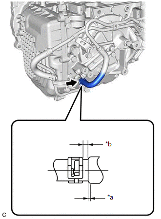
5. CONNECT INLET NO. 1 OIL COOLER HOSE
(a) Connect the inlet No. 1 oil cooler hose to the No. 1 oil cooler outlet tube sub-assembly and slide the clip to secure it. NOTICE: Make sure to slide the inlet No. 1 oil cooler hose until it contacts the hose stopper of the No. 1 oil cooler outlet tube sub-assembly. |
|
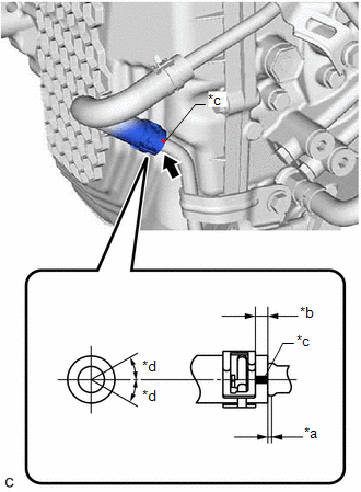
6. CONNECT OUTLET NO. 1 OIL COOLER HOSE
(a) Connect the outlet No. 1 oil cooler hose to the oil cooler union sub-assembly and slide the clip to secure it. NOTICE:
|
|
7. INSTALL BATTERY CLAMP SUB-ASSEMBLY
Click here 
8. INSTALL ECM
Click here
9. INSTALL BATTERY
Click here
10. ADD ENGINE COOLANT
Click here
11. ADJUST AUTOMATIC TRANSAXLE FLUID
Click here
12. INSPECT FOR OIL LEAK
13. INSPECT FOR COOLANT LEAK
Click here
14. INSTALL FRONT FENDER APRON SEAL LH
Click here
15. INSTALL REAR ENGINE UNDER COVER LH
Click here
16. INSTALL NO. 1 ENGINE UNDER COVER
Click here
17. INSTALL FRONT WHEEL OPENING EXTENSION PAD LH
Click here
18. INSTALL FRONT WHEEL OPENING EXTENSION PAD RH
Click here
19. INSTALL FRONT WHEEL LH
Click here
Removal
REMOVAL
The necessary procedures (adjustment, calibration, initialization or registration) that must be performed after parts are removed and installed, or replaced during transmission oil cooler removal/installation are shown below.
Necessary Procedures After Parts Removed/Installed/ReplacedReplaced Part or Performed Procedure | Necessary Procedure | Effect/Inoperative Function when Necessary Procedure not Performed | Link |
|---|---|---|---|
Battery terminal is disconnected/reconnected |
Perform steering sensor zero point calibration |
Lane Departure Alert System (w/ Steering Control) |
 |
Pre-collision System |
|||
Intelligent Clearance Sonar System*1 |
|||
Lighting System (for Gasoline Model with Cornering Light) |
|||
Memorize steering angle neutral point |
Parking Assist Monitor System |
|
|
Panoramic View Monitor System |
|
||
Replacement of ECM |
Vehicle Identification Number (VIN) registration |
MIL comes on |
|
ECU communication ID registration (Immobiliser system) |
Engine start function |
|
|
Replacement of ECM (If transaxle compensation code read from ECM) |
|
|
|
Replacement of ECM (If transaxle compensation code not read from ECM) |
|
||
Replacement of ECM |
Code registration (Smart key System (for Start Function)) |
|
|
Replacement of automatic transaxle fluid |
ATF thermal degradation estimate reset |
The value of the Data List item "ATF Thermal Degradation Estimate" is not estimated correctly |
|
- *1: When performing learning using the Techstream.
Click here
- *2: Not necessary when ECM replaced with new one
PROCEDURE
1. REMOVE BATTERY
Click here
2. REMOVE ECM
Click here
3. REMOVE BATTERY CLAMP SUB-ASSEMBLY
Click here
4. REMOVE FRONT WHEEL LH
Click here
5. REMOVE FRONT WHEEL OPENING EXTENSION PAD LH
Click here
6. REMOVE FRONT WHEEL OPENING EXTENSION PAD RH
Click here
7. REMOVE NO. 1 ENGINE UNDER COVER
Click here
8. REMOVE REAR ENGINE UNDER COVER LH
Click here
9. REMOVE FRONT FENDER APRON SEAL LH
Click here
10. DRAIN ENGINE COOLANT
Click here
11. DRAIN AUTOMATIC TRANSAXLE FLUID
Click here
12. DISCONNECT OUTLET NO. 1 OIL COOLER HOSE
(a) Slide the clip and disconnect the outlet No. 1 oil cooler hose from the oil cooler union sub-assembly. HINT: Use a container to catch any automatic transaxle fluid which flows out of the outlet No. 1 oil cooler hose and oil cooler union sub-assembly. |
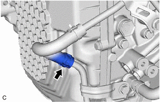 |
13. DISCONNECT INLET NO. 1 OIL COOLER HOSE
(a) Slide the clip and disconnect the inlet No. 1 oil cooler hose from the No. 1 oil cooler outlet tube sub-assembly. HINT: Use a container to catch any automatic transaxle fluid which flows out of the inlet No. 1 oil cooler hose and No. 1 oil cooler outlet tube sub-assembly. |
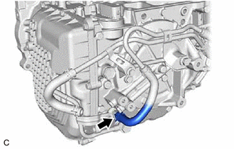 |
14. REMOVE NO. 1 OIL COOLER TUBE SUB-ASSEMBLY WITHOUT HOSE
(a) Remove the 2 bolts to disconnect the No. 1 oil cooler tube sub-assembly without hose from the automatic transaxle case sub-assembly. |
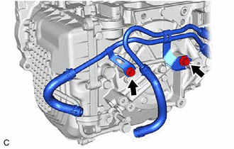 |
(b) Slide the clip and disconnect the inlet No. 2 oil cooler hose from the transmission oil cooler. HINT: Use a container to catch any automatic transaxle fluid which flows out of the inlet No. 2 oil cooler hose and transmission oil cooler. |
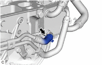 |
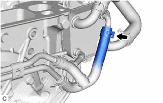
(c) Slide the clip and disconnect the outlet No. 2 oil cooler hose to remove the No. 1 oil cooler tube sub-assembly without hose from the transmission oil cooler. HINT: Use a container to catch any automatic transaxle fluid which flows out of the outlet No. 2 oil cooler hose and transmission oil cooler. |
 |
(d) Slide the 4 clips and remove the inlet No. 1 oil cooler hose, inlet No. 2 oil cooler hose, outlet No. 1 oil cooler hose and outlet No. 2 oil cooler hose from the No. 1 oil cooler tube sub-assembly without hose. |
|
15. DISCONNECT NO. 1 WATER BY-PASS HOSE
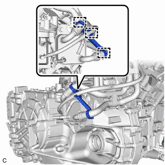
(a) Disengage the 3 clamps to remove the transmission breather clamp. |
 |
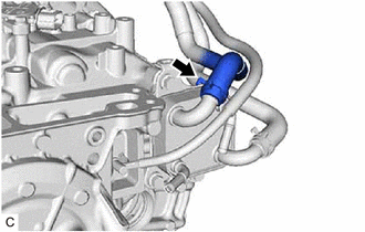
(b) Slide the clip and disconnect the No. 1 water by-pass hose from the transmission oil cooler. HINT: Use a container to catch any coolant which flows out of the No. 1 water by-pass hose and transmission oil cooler. |
 |
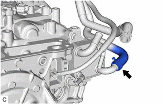
16. DISCONNECT WATER BY-PASS HOSE ASSEMBLY
(a) Slide the clip and disconnect the water by-pass hose assembly from the transmission oil cooler. HINT: Use a container to catch any coolant which flows out of the water by-pass hose assembly and transmission oil cooler. |
 |
17. REMOVE TRANSMISSION OIL COOLER
(a) Remove the 3 bolts. |
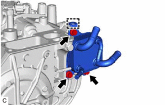 |
(b) Disengage the hook to remove the transmission oil cooler from the automatic transaxle case sub-assembly.
HINT:
Use a container to catch any coolant and automatic transaxle fluid which flow out of the transmission oil cooler.