U140f automatic transaxle
Disassembly
In this manual: U140f automatic transaxle
139steps
~914min
5/5difficulty
16special tools
Done 0 of 139
- Remove park/neutral position switch assembly
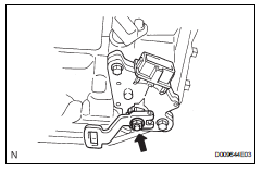
- Remove the nut, washer and control shaft lever.
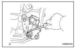
- Using a screwdriver, pry off the lock plate.
- Remove the nut and lock plate.
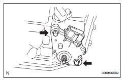
- Remove the 2 bolts and pull out the switch.
- Remove breather plug hose
- Remove oil cooler outlet tube union
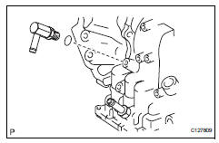
- Remove the union.
- Remove the o-ring from the union.
- Remove oil cooler inlet tube union
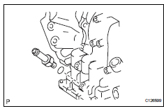
- Remove the union.
- Remove the o-ring from the union.
- Remove speed sensor

- Remove the 2 bolts and 2 transmission revolution sensors from the transaxle.
- Remove the 2 o-rings from the sensors.
- Remove no. 1 Transaxle case plug

- Remove the 4 plugs from the transaxle.
- Remove the 4 o-rings from the 4 plugs.
- Place transaxle on wooden blocks
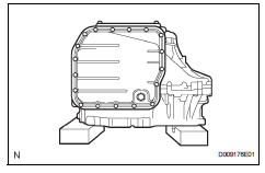
- Remove automatic transaxle oil pan subassembly
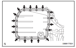
- Remove the 18 bolts.
- Remove the oil pan and 3 magnets.
- Remove the gasket from the oil pan.
- Inspect automatic transaxle oil pan subassembly (see page ax-184)
- Remove valve body oil strainer assembly
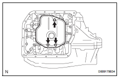
- Remove the 3 bolts and oil strainer.
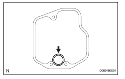
- Remove the o-ring from the oil strainer.
- Remove transmission wire

- Disconnect the 5 shift solenoid valve connectors.
- Remove the bolt, lock plate and atf temperature sensor.
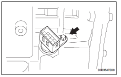
- Remove the bolt and transaxle wire.
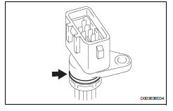
- Remove the o-ring from the transaxle wire.
- Remove transmission valve body assembly

- Support the valve body and remove the 17 bolts and valve body.
- Remove no. 1 Governor apply gasket
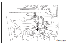
- Remove the governor apply gasket from the transaxle case.
- Remove transaxle case 2nd brake gasket
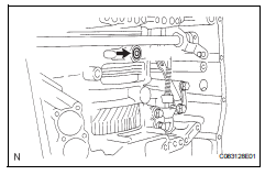
- Remove the 2nd brake gasket from the transaxle.
- Remove brake drum gasket
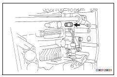
- Remove the brake drum gasket from the transaxle.
- Remove check ball body
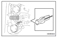
- Remove the check ball and spring from the transaxle.
- Remove c-3 accumulator piston
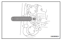
- Remove the spring from the c-3 accumulator piston.
- Apply compressed air (392 kpa, 4.0 Kgf/cm2, 57 psi) to the oil hole and remove the c-3 accumulator piston.
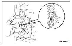
Notice:
- Applying compressed air may cause the piston to jump out. When removing the piston, hold it with your hand using a waste cloth.
- Make sure not to spatter atf when applying compressed air.
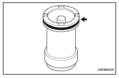
- Remove the o-ring from the c-3 accumulator piston.
- Remove c-1 accumulator piston
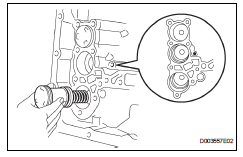
- Apply compressed air (392 kpa, 4.0 Kgf/cm2, 57 psi) to the oil hole and remove the c-1 accumulator piston and spring.
- Applying compressed air may cause the piston to jump out. When removing the piston, hold it with your hand using a waste cloth.
- Make sure not to spatter atf when applying compressed air.
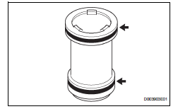
- Remove the 2 o-rings from the c-1 accumulator piston.
- Remove b-3 accumulator piston

- Apply compressed air (392 kpa, 4.0 Kgf/cm2, 57 psi) to the oil hole and remove the b-3 accumulator piston and 2 springs.
- Applying compressed air may cause the piston to jump out. When removing the piston, hold it with your hand using a waste cloth.
- Make sure not to spatter atf when applying compressed air.
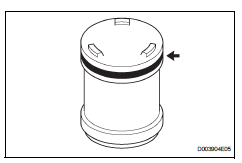
- Remove the o-ring from the b-3 accumulator piston.
- Remove manual detent spring subassembly
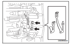
- Remove the 2 bolts, manual detent spring and cover.
- Remove parking lock pawl bracket

- Remove the 2 bolts and parking lock pawl bracket.
- Remove manual valve lever shaft retainer spring

- Using needle-nose pliers, remove the retainer spring.
- Remove manual valve lever sub-assembly
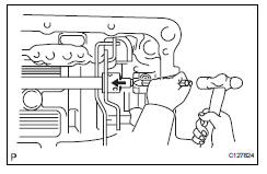
- Using a chisel and hammer, unstake and remove the spacer.
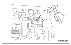
- Using a pin punch and hammer, tap out the pin.
Slowly tap out the pin so that it will not fall into the transaxle.
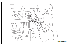
- Remove the manual valve lever shaft and manual valve lever.
- Remove parking lock rod sub-assembly

- Remove the parking lock rod from the manual valve lever.
- Remove manual valve lever shaft oil seal
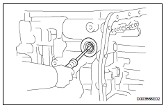
- using a screwdriver, pry out the oil seal from the transaxle.
- Fix automatic transaxle assembly
- Fix the transaxle case with the oil pump side facing up.
- Inspect input shaft end play (see page ax- 184)
- Remove no. 1 Transaxle case plug

- Remove the 2 plugs.
- Remove the 2 o-rings from the 2 plugs.
- Remove transaxle housing
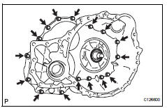
- Remove the 16 bolts.
- Tap on the circumference of the transaxle housing with a plastic-faced hammer to remove the transaxle housing from the transaxle case.
The differential may be accidentally removed when the transaxle housing is removed.
- Remove oil pump assembly

- Remove the 7 bolts and oil pump from the transaxle.
- Remove thrust needle roller bearing
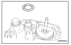
- Remove thrust needle roller bearing from the underdrive planetary gear.
- Remove no. 2 Thrust bearing underdrive race
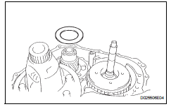
- Remove the thrust bearing underdrive race from the underdrive planetary gear.
- Remove differential gear assembly
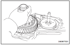
- Remove the differential gear form the transaxle.
- Remove overdrive brake gasket

- Remove the 2 overdrive brake gaskets from the transaxle.
- Remove forward clutch assembly
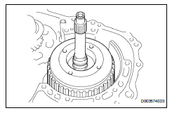
- Remove the forward clutch from the transaxle.

- Remove the thrust bearing from the forward clutch.
- Remove multiple disc clutch hub
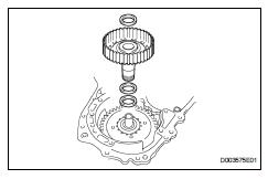
- Remove the thrust bearing, multiple clutch hub, needle roller bearing and bearing race from the transaxle.
- Inspect multiple disc clutch hub (see page ax-184)
- Remove underdrive planetary gear assembly
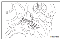
- Remove the bolt and parking pawl shaft clamp.
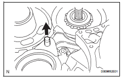
- Remove the parking lock pawl shaft.
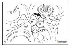
- Push the parking lock pawl.
Failure to do so will cause interference when the underdrive planetary gear is removed.
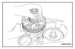
- Remove the underdrive planetary gear from the transaxle.
Be careful so that the underdrive planetary gear assembly will not fall out.

- Remove the spring, pawl pin and parking lock pawl.
- Remove underdrive clutch assembly

- Remove the underdrive clutch, thrust bearing and bearing race from the transaxle.
- Remove underdrive 1-way clutch assembly
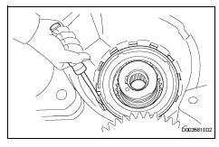
- Using a screwdriver, pry out the snap ring from the transaxle.
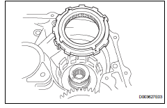
- Remove the 1-way clutch from the transaxle.

- Remove the outer race retainer from the 1-way clutch.
- Remove no. 2 Underdrive clutch disc
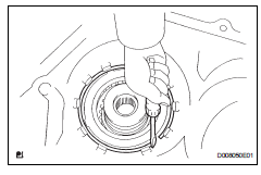
- Using a screwdriver, pry out the snap ring.
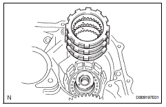
- Remove the flange, 3 discs and 3 plates from the transaxle.
- Inspect no. 2 Underdrive clutch disc (see page ax-185)
- Remove underdrive brake return spring sub-assembly
- Using sst, a snap ring expander and press, remove the snap ring and piston return spring.
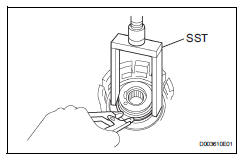
- Inspect underdrive brake return spring sub-assembly (see page ax-185)
- Remove no. 1 Transaxle case plug
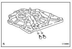
- Remove the 2 plugs from the transaxle rear cover.
- Remove the 2 o-rings from the 2 plugs.
- Remove transaxle rear cover subassembly
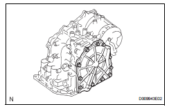
- Remove the 11 bolts.
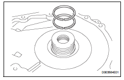
- Tap in the circumference of the rear cover with a plastic-fased hammer to remove the transaxle rear cover from the transaxle.
- Remove the 2 oil seal rings from the transaxle rear cover.
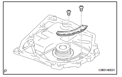
- Using a t30 ''torx'' socket wrench, remove the 2 screws and transaxle rear cover plate.
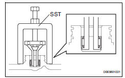
- Using sst, remove the needle-roller bearing from the transaxle rear cover.
- Remove brake apply tube
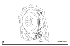
- Remove the bolt, clamp and 2 brake apply tubes.
- Remove the brake apply tube from the clamp.
- Remove front clutch apply tube
- Remove the front clutch apply tube from the clamp.
- Remove no. 1 Governor apply gasket
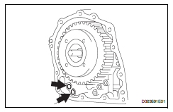
- Using a screwdriver, remove the 2 apply gaskets.
- Remove direct clutch assembly
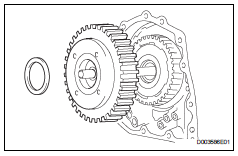
- Remove the thrust bearing and direct clutch from the transaxle.
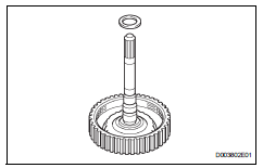
- Remove the bearing race from the direct clutch.
- Remove rear planetary sun gear assembly
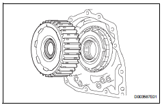
- Remove the rear planetary sun gear from the transaxle.
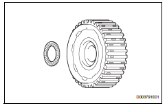
- Remove the thrust bearing from the rear planetary sun gear.
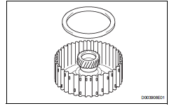
- Remove the no. 1 Thrust washer from the rear planetary sun gear.
- Remove 1-way clutch assembly
- Remove the 1-way clutch and thrust bearing from the transaxle.

- Remove the inner race from the 1-way clutch.
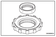
- Remove 1-way clutch outer sleeve
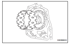
- Remove 2nd brake clutch disc
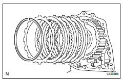
- Using a screwdriver, remove the snap ring.
- Remove the flange, 3 discs and 3 plates from the transaxle.
- Inspect 2nd brake clutch disc (see page ax- 185)
- Remove 2nd brake piston assembly

- Using a screwdriver, remove the snap ring.
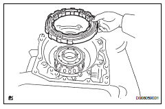
- Remove the 2nd brake piston from the transaxle.
- Remove rear planetary gear assembly
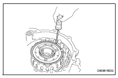
- Using a screwdriver, pry out the snap ring.
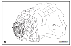
- Remove the rear planetary gear from the transaxle.
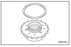
- Remove the no. 1 Planetary carrier thrust washer from the rear planetary gear.
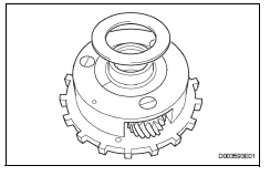
- Remove the bearing race from the rear planetary gear.
- Remove input sun gear
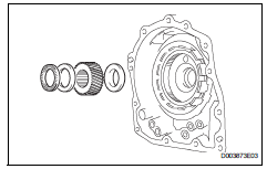
- Remove the 2 thrust bearings, bearing race and input sun gear from the transaxle.
- Remove front planetary gear assembly
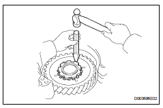
- Using a chisel and hammer, unstake the lock washer.
Push down all claws of the washer. Otherwise sst cannot be fully pressed against the nut and cannot loosen the nut.
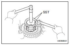
- Using sst, remove the nut.
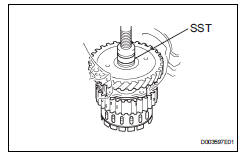
- Using sst and a press, remove the front planetary gear from the counter drive gear.
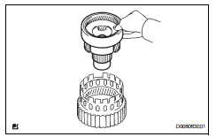
- Remove the front planetary gear from the brake hub.
- Remove front planetary ring gear
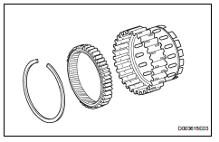
- Using a screwdriver, remove the snap ring and front planetary ring gear from the brake hub.
- Remove 1st and reverse brake clutch disc
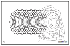
- Remove the flange, 5 discs and 5 plates from the transaxle case.
- Inspect 1st and reverse brake clutch disc (see page ax-185)
- Remove 1st and reverse brake return spring sub-assembly
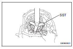
- Using sst, a press and snap ring expander, remove the snap ring and piston return spring.
- Stop the press when the spring sheet is lowered 1 to 2 mm (0.039 To 0.078 In.) From the snap ring groove, preventing the spring sheet from deforming.
- Do not expand the snap ring excessively.
- Inspect 1st and reverse brake return spring sub-assembly (see page ax-186)
- Remove 1st and reverse brake piston
- Apply compressed air (392 kpa, 4.0 Kgf/cm2, 57 psi) to the transaxle case to remove the 1st and reverse brake piston.
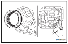
Notice:
- Applying compressed air may cause the piston to jump out. When removing the piston, hold it with your hand using a waste cloth.
- Make sure not to spatter atf when applying compressed air.
- Remove the 2 o-rings from the 1st and reverse brake piston.
- Remove counter drive gear
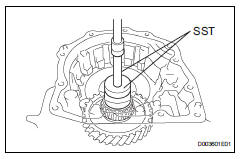
- Using sst and a press, remove the counter drive gear from the transaxle case.
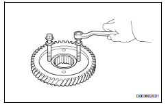
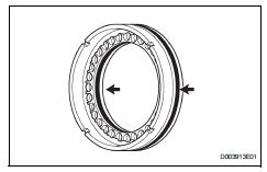
- As shown in the illustration, tighten the 2 bolts evenly and make a clearance of approximately 20.0 Mm (0.797 In.) Between the counter drive gear and the inner race.
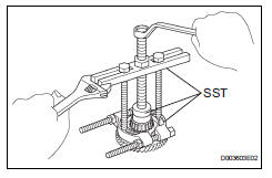
- Using sst, remove the tapered roller bearing.
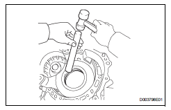
- Using a brass bar and hammer, tap out the 2 bearing outer races.
- Remove counter drive gear hole snap ring
- Using a screwdriver, pry out the snap ring from the transaxle.

- Remove no. 2 Breather plug
- Remove underdrive brake piston
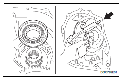
- Apply compressed air (392 kpa, 4.0 Kgf/cm2, 57 psi) to the transaxle case to remove the underdrive brake piston.
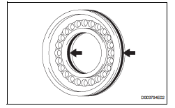
- Using sst, remove the needle-roller bearing from the transaxle
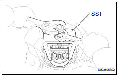
- Remove underdrive clutch drum oil seal ring
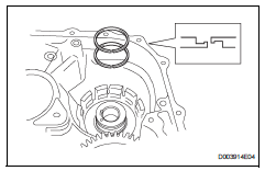
- Remove the 2 oil seal rings from the transaxle.
- Remove underdrive cylindrical roller bearing
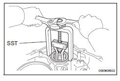
- Using sst, remove the cylindrical roller bearing from the transaxle.
- Remove underdrive output shaft oil seal ring
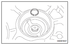
- Remove the oil seal ring from the transaxle housing.
- Remove differential gear lube apply tube

- Remove the bolt, clamp and apply tube from the transaxle.
Test yourself
A quick Toyota RAV4 quiz: every answer comes with an explanation and a link to the manual page.
Was this page helpful?