Audio / visual
Display Signal Circuit between Video Terminal and Television Display
In this manual: Audio / visual
6steps
~36min
2/5difficulty
Done 0 of 6
DESCRIPTION
This is the display signal circuit from the video terminal to the television display assembly.
WIRING DIAGRAM
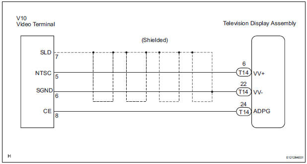
INSPECTION PROCEDURE
1 CHECK HARNESS AND CONNECTOR (TELEVISION DISPLAY ASSEMBLY - VIDEO TERMINAL)
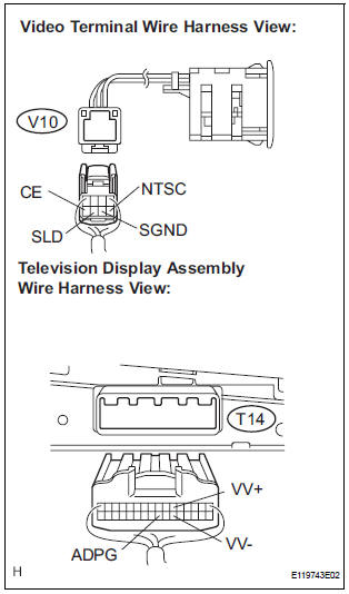
- Disconnect the connectors from the video terminal and television display assembly.
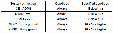
- Measure the resistance according to the value(s) in the table below.
Standard resistance
2 INSPECT VIDEO TERMINAL
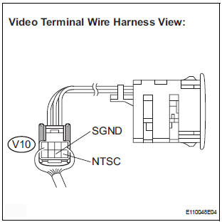
- Reconnect the video (video adapter) terminal connector.
- Measure the waveform according to the table below.
OK

HINT: The waveform pattern may differ from that shown in the illustration below due to differences in oscilloscope setting. A normal video terminal operating condition can be determined if any waveform is output.
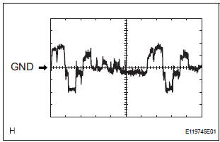
- Oscilloscope waveform
- Terminal: NTSC - Body ground
Setting: 200mV/DIV, 10 μs/DIV
Condition: DVD display is ON.
PROCEED TO NEXT CIRCUIT INSPECTION SHOWN IN PROBLEM SYMPTOMS TABLE
Test yourself
A quick Toyota Sienna quiz: every answer comes with an explanation and a link to the manual page.
Was this page helpful?