Steering Column
PROCEDURE
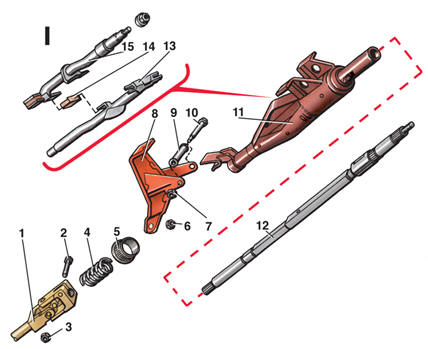
Steering Columns 1 – universal joint; 2 – bolt; 3 – nut; 4 – spring; 5 – lower bearing; 6 – nut; 7 – nut; 8 – bracket; 9 – bushing; 10 – bolt; 11 – steering column housing; 12 – steering column shaft; 13 – lower steering column shaft; 14 – rubber gasket; 15 – upper steering column shaft; I – steering columns of models produced before 07.1984
Detailed information on custom-made children's rooms is available on our website.
Instrument Panel Upper Shelf Mounting 1 – lower instrument panel cover; 2 – screw; 3 – instrument panel; 4 – fuse box cover
Removal PROCEDURE 1. Disconnect the negative battery cable. 2. Remove the steering wheel (see subsection 8.4). 3. Remove screws 2 (see illustration Upper Shelf Mounting). 4. Remove lower instrument panel cover 1. 5. Remove the three screws 7 (see illustration Steering Wheel) and remove the steering column switch. 6. Disconnect the electrical wires. 7. Remove the bolts and remove lower steering column cover 17. 8. Remove the steering column mounting bolts. 9. Remove bolt 2 (see illustration Steering Columns). 10. Remove bolt 10 from the bracket. 11. Remove the steering column together with spring 4.
Warning: On vehicles built until 07.1984, a two-piece steering column shaft was installed. 12. Remove washer 9 (see figure Steering Wheel). 13. Remove spring 10 and upper bearing 11. 14. Disconnect connector from contact group 15. 15. Unscrew bolt 16. 16. Remove ignition lock housing 14 with the key inserted in the ignition lock (the lock must be released in this process). 17. Remove steering column shaft 12 (see figure Steering Columns) and lower bearing 5. 18. Separate upper 15 and lower 13 steering column shafts (for vehicles built until July 1984) and remove rubber spacers 14. 19. Remove shafts 13 and 15 from steering column housing 11. Assembly and Installation PROCEDURE 1. Assemble and install the steering column in the reverse order of disassembly and removal. 2. Lubricate the bearings with multi-purpose grease. 3. Install a new locking washer 9 (see figure Steering Wheel) until it stops. 4. For vehicles built until July 1984, compress upper 15 and lower 13 shafts with special tool and install new locking washer 9 (see figure Steering Wheel) until it stops. 5. For vehicles built until July 1984, clamp the lower part of the shaft in a vise so that the upper part rests on the vise jaws and both halves cannot move relative to each other. The pin located in the lower part of the shaft must be visible in the hole of the upper part. If necessary, extend both parts until they stop. 6. Check operation of the steering wheel, combination switch and horn.
Test yourself
A quick Volkswagen Golf quiz: every answer comes with an explanation and a link to the manual page.