Lower control arm, ball joint
Assembly overview - lower control arm, ball joint

Note
- Welding and straightening work on load-bearing and wheel-guiding components of the wheel suspension is not permitted.
- Always replace self-locking nuts.
- Always replace corroded bolts/nuts.
- Rubber-metal bearings have a limited rotation range. Therefore, only tighten the bolted connections on components with rubber-metal bearings once the wheel bearing housing is raised (unladen position).
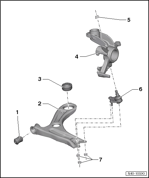
- Front rubber-metal bushing
- Remove and install
- Lower control arm
- if damaged, replace ball joint as well
- Remove and install
- Rear rubber-metal bushing
- Remove and install
- Wheel bearing housing
- Remove and install
- If wheel bearing housing is replaced, vehicle must be measured afterward
- different versions
- Assignment → Electronic Parts Catalog "ETKA"
- Nut
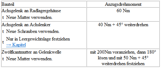
- 60 N·m
- Ball joint
- check
- Remove and install
- if control arm is damaged, replace it
- Nut
- Turn further by 40 N·m + 45º
Removing and installing lower control arm
Required Special Tools, Test and Measuring Equipment and Auxiliary Items
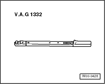
- Torque Wrench -V.A.G 1332-
Carry out the following work:
Removing
- Loosen wheel bolts.
- Raise the vehicle.
- Remove wheel.
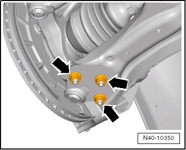
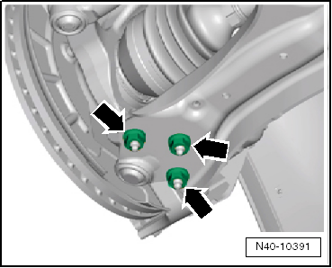
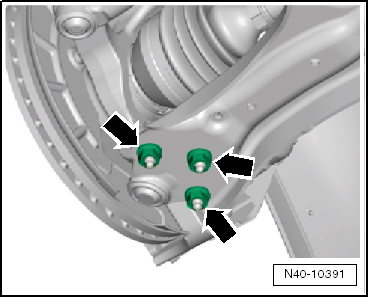
- Unscrew nuts -arrows-.
- Pull control arm out of the ball joint and turn wheel bearing housing outward to relieve the control arm.
- Unscrew bolts -arrows-.
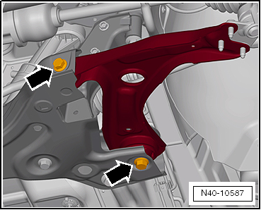
- Swing control arm rearward and pull it out of the subframe in direction of arrow.
Installing
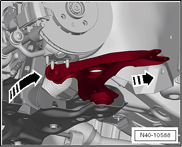
- Insert rear end of control arm into subframe in direction of arrow and swing it forward.
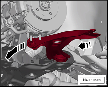
- Insert bolts in direction of arrows and tighten.
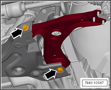
- Insert ball joint into control arm and tighten nuts at arrows.
Use new nuts!
Installation is carried out in reverse order.
- Install wheel and tighten.
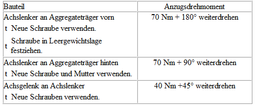
Tightening torques
Replacing lower control arm rubber-metal bushing
Replacing front rubber-metal bushing for lower control arm
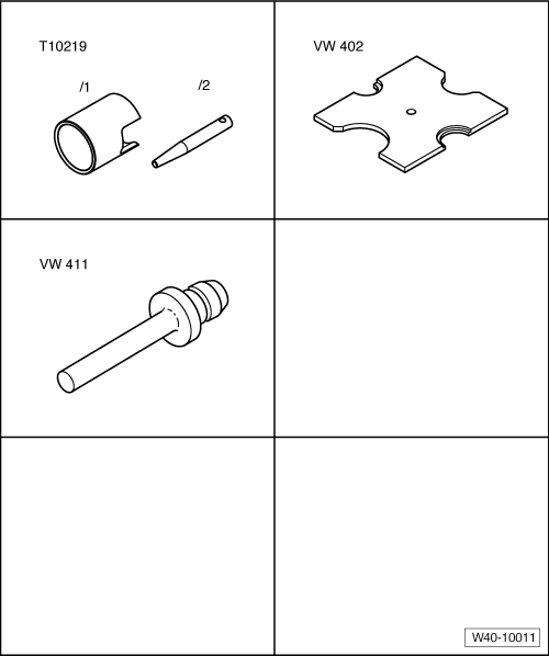
Required Special Tools, Test and Measuring Equipment and Auxiliary Items
- Mandrel -T10219/2-
- Pressure plate -VW 402-
- Pressure ram -VW 411-
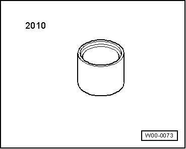
- Tube section -2010-
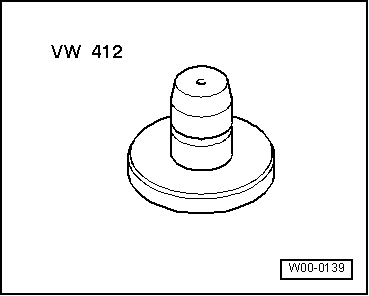
- Pressure ram -VW 412-
Carry out the following work:
- Remove control arm.
Pressing out rubber-metal bushing
- Press out rubber-metal bushing as shown in illustration.
- Pressure ram -VW 411-
- Tube section -2010- (large inner diameter toward control arm)
- Pressure plate -VW 402-
Pressing in rubber-metal bushing
- Apply assembly lubricant -G 294 421 A1- to outside of rubber-metal bushing.
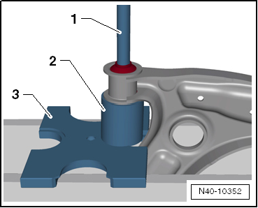
- Press in rubber-metal bushing as shown in illustration.
- Mandrel -T10219/2-
- Rubber-metal bushing
- Tube section -2010- (large inner diameter toward control arm)
- Pressure plate -VW 402-

Note
At the start of the pressing-in process, the rubber-metal bushing briefly sits at an angle. It then straightens again as it continues. It does not need to be guided further.
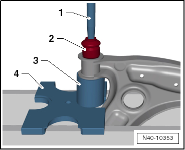
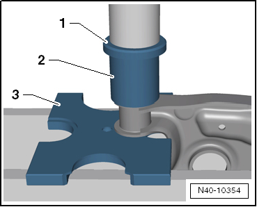
- Press in rubber-metal bushing until core -1- and bore in control arm -2- are at the same level.
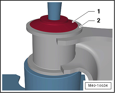
- Press bushing back slightly in control arm.
- Pressure ram -VW 412-
- Tube section -2010- (large inner diameter toward control arm)
- Pressure plate -VW 402-
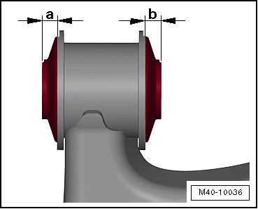
Dimensions -a- and -b- must be the same.
- Install control arm.
Replacing rear rubber-metal bushing for lower control arm
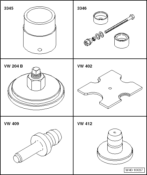
Required Special Tools, Test and Measuring Equipment and Auxiliary Items
- Tube for wheel bearing -3345-
- Assembly tool -3346-
- Pulling tool for crankshaft seal -VW 204 B-
- Pressure plate -VW 402-
- Pressure ram -VW 409-
- Pressure ram -VW 412-
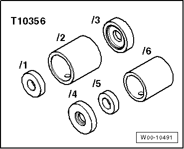
- Assembly tool -T10356-
Carry out the following work:
- Remove control arm.
Pressing out rubber-metal bushing
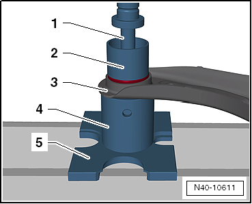
- Press out rubber-metal bushing as shown in illustration.
- Pressure ram -VW 409-
- Pressure piece -3346/1-
- Control arm - the opening of the control arm must point upward
- Pressure piece -T10356/2-
- Pressure plate -VW 402-
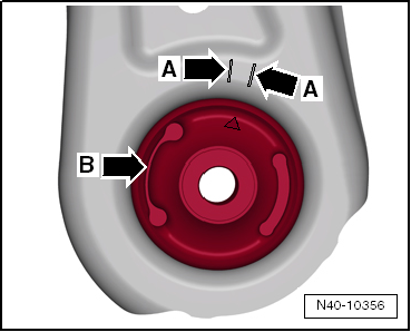
Installation position of rear bushing in control arm
One of the embossed arrows points between the two markings -arrows A- in the control arm.
The cam -arrow B- must always point toward the outside of the vehicle.
Pressing in rubber-metal bushing
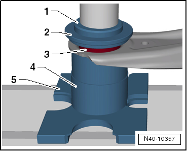
- Press in rubber-metal bushing as shown in illustration.
- Pressure ram -VW 412-
- Pulling tool for crankshaft seal -VW 204 B-
- Rubber-metal bushing
- Tube for wheel bearing -3345- (small outer diameter toward control arm)
- Pressure plate -VW 402-

Note
Press in rubber-metal bushing until the pressure piece of the pulling tool for crankshaft seal -VW 204 B- rests on the control arm.
- Install control arm.
Checking ball joint
Checking axial play
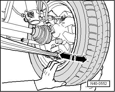
- Pull control arm firmly down in direction of arrow and push it back up.
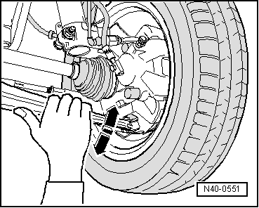
Checking radial play
- Push bottom of wheel firmly inward and outward in direction of arrow.

Note
- No play that can be felt or seen may be present during either test.
- Watch the ball joint during the tests.
- Take into account any wheel bearing play or "play" in the upper strut mount.
- Check boot for damage, replace ball joint if necessary.
Removing and installing ball joint
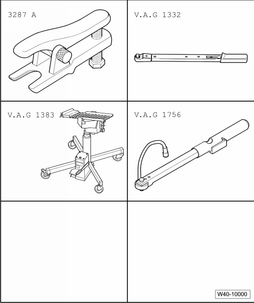
Required Special Tools, Test and Measuring Equipment and Auxiliary Items
- Ball joint puller -3287A-
- Torque Wrench -V.A.G 1332-
- Engine and Transmission Hoist -V.A.G 1383 A-
- Torque angle wrench -V.A.G 1756-
- Ejector -T10520-
Carry out the following work:
Removing
- Raise vehicle until front axle is relieved of load.
- Also loosen 12-point nut for drive shaft.

Caution!
If wheel-side driveshaft bolt connection is loose, wheel bearings must not be loaded.
If the wheel bearings are loaded by the weight of the vehicle, they will be pre-damaged. This reduces the service life of the wheel bearings.
The bolt for the driveshaft may be loosened by a maximum of 90º if the vehicle is standing on its wheels.
Vehicles without driveshaft must not be moved, otherwise the wheel bearing will be damaged. If a vehicle must nevertheless be moved, observe the following:
- Install an outer CV joint instead of the driveshaft.
- Tighten outer CV joint to 120 N·m.
- Loosen wheel bolts.
- Raise the vehicle.
- Remove wheel.
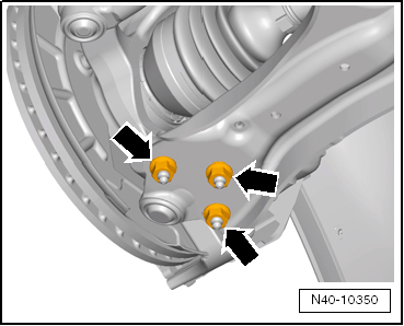
- Unscrew nuts -arrows-.
- Pull control arm out of ball joint.
- Pull control arm down as far as necessary.
- Pull drive shaft completely out of wheel hub.
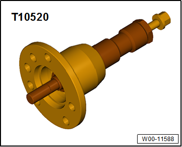
If the driveshaft cannot be pulled out of the wheel bearing, press the driveshaft out of the wheel bearing with puller -T10520-.
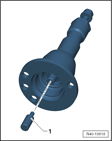
Before using extractor -T10520-, make sure pressure piece -1- is fitted.
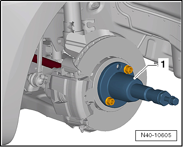
Operating extractor -T10520-:
- Attach puller -T10520--1- to wheel hub with 2 wheel bolts.
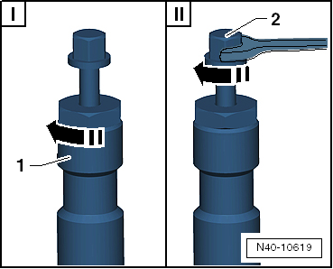
- Be sure to observe the specified sequence.
- Tighten knurled nut -1- by hand.
- Turn only bolt -2- with a wrench and press drive shaft out with extractor -T10520-.

Note
At the end of the procedure, or before retightening, return the spindle to its starting position so the hydraulic action can be used!
- Secure drive shaft to body.

Note
Place engine and transmission jack -V.A.G 1383 A- or similar under vehicle (risk of accident from falling parts when pressing out the ball joint).
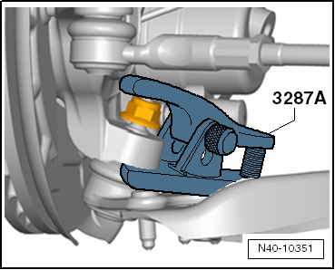
- Loosen nut for ball joint.

Caution!
Leave nut a few turns on the stud to protect the thread.
- Position ball joint puller -3287 A- as shown in illustration and press out ball joint.
Installing
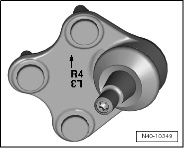
Observe installation position of ball joints!
Left ball joint
Arrow marked "L4" points in direction of travel.
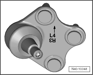
Right ball joint
Arrow marked "R4" points in direction of travel.
Observe the exact installation position of the ball joints!
If installed in the wrong position, caster will be incorrect.
- Insert ball joint into wheel bearing housing.
- Screw on new self-locking nut while holding ball joint with internal Torx -T40-.
- Install the driveshaft into the wheel hub.
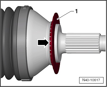
Make sure that deflector disc -1- is fully clipped onto outer CV joint.

Note
- The lugs of deflector disc -1- must point toward outer CV joint.
- Deflector disc -1- must contact the contact surface of outer CV joint -arrow-.

Note
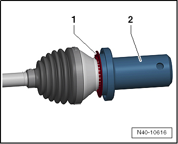
If deflector disc -1- is not positioned correctly or has fallen off outer CV joint, drive it onto outer CV joint up to the stop with pressure piece -T10049-.
- Tighten the nuts -arrows-.

Note
Make sure the bellows are undamaged and not twisted.
- Install wheel and tighten.
- Coat the thread and splines of the stub axle and the contact surface between wheel hub and 12-point nut with pressure-resistant oil Fuchs Renolin B15 VG46.
- Tighten 12-point nut for driveshaft.
Tightening torques