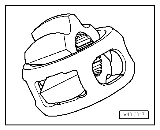
Driveshaft
Assembly Overview - Driveshaft
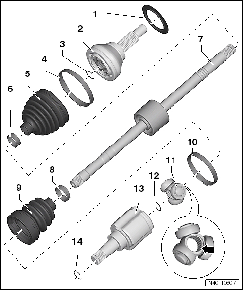
- Deflector disc
- Before installing the driveshaft, check that the deflector disc is correctly seated
- Outer constant velocity joint
- only replace as a complete unit
- remove
- install: Using a plastic hammer, drive onto the shaft until the spring-loaded circlip snaps out
- check
- Circlip
- insert into the groove of the shaft
- Clamp
- replace after every removal
- different versions
- Assignment → Electronic Parts Catalog "ETKA"
- tension
- Constant velocity joint boot, outer
- check for cracks and chafing
- Material: Hytrel (polyelastomer)
- Before installing on the constant velocity joint, coat the sealing surface with -D 454 300 A2-
- Clamp
- replace after every removal
- tension
- Driveshaft
- Clamp
- replace after every removal
- tension
- Constant velocity joint boot, tripod joint
- check for cracks and chafing
- Clamp
- replace after every removal
- tension
- Tripod star with rollers
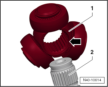
The chamfer -arrow- points toward the splines of the driveshaft.
- Circlip
- replace after every removal
- Joint housing
- Circlip
- insert into the groove of the joint housing
Removing and installing driveshaft
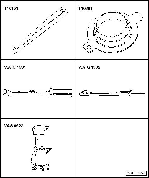
Required Special Tools, Test and Measuring Equipment and Auxiliary Items
- Wedge -T10161-
- Sealing cap -T10381-
- Torque Wrench -V.A.G 1331-
- Torque Wrench -V.A.G 1332-
- Oil drain and suction unit -VAS 6622-
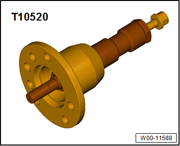
- Ejector -T10520-

Caution!
If wheel-side driveshaft bolt connection is loose, wheel bearings must not be loaded.
If the wheel bearings are loaded by the weight of the vehicle, they will be pre-damaged. This reduces the service life of the wheel bearings.
The bolt for the driveshaft may be loosened by a maximum of 90º if the vehicle is standing on its wheels.
Vehicles without driveshaft must not be moved, otherwise the wheel bearing will be damaged. If a vehicle must nevertheless be moved, observe the following:
- Install an outer CV joint instead of the driveshaft.
- Tighten outer CV joint to 120 N·m.
Carry out the following work:
Removing
- Raise vehicle until front axle is relieved of load.
- Unscrew the 12-point nut of the driveshaft.
- Loosen wheel bolts.
- Raise the vehicle.
- Remove wheel.
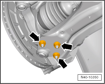
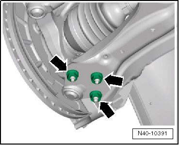
- Unscrew nuts -arrows-.
- Pull control arm out of ball joint.
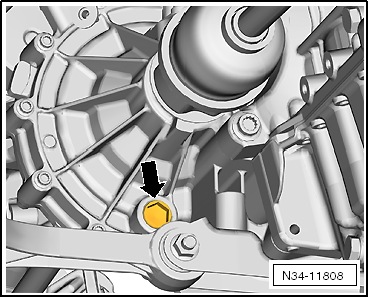
- Drain the transmission oil -arrow-.
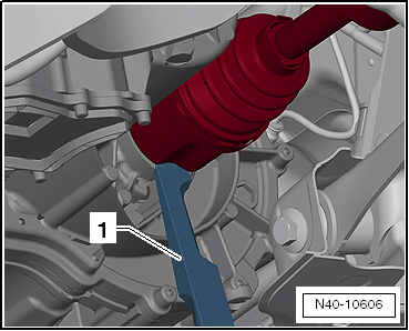
- Place the wedge -T10161- -1- between the transmission housing and the tripod joint.
- Drive the inner joint out of the transmission by striking the wedge -T10161- with a rubber mallet.
- Remove the driveshaft from the transmission.
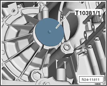
- Insert sealing cap -T10381/1- into the transmission.
- Pull the driveshaft out of the wheel bearing and remove it.
If the driveshaft cannot be pulled out of the wheel bearing, it can be pressed out of the wheel bearing using puller -3283 A- or puller -T10520-.
Before using extractor -T10520-, make sure pressure piece -1- is fitted.
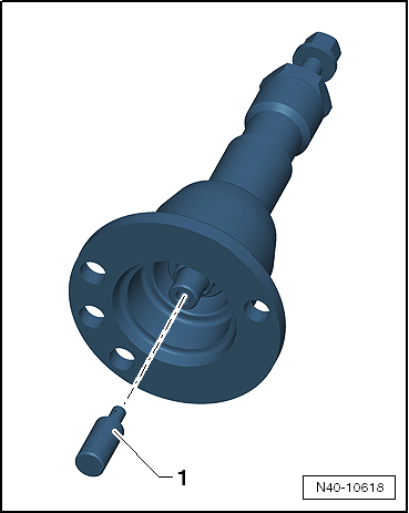
Operating extractor -T10520-:
- Attach puller -T10520--1- to wheel hub with 2 wheel bolts.
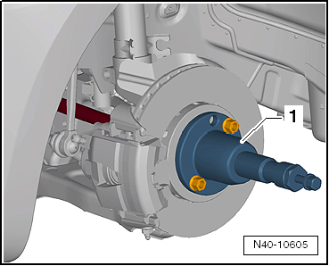
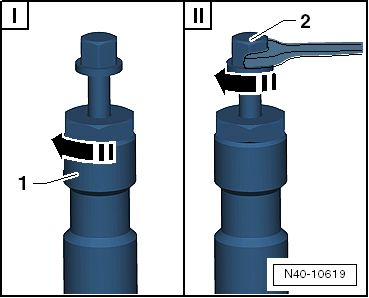
- Be sure to observe the specified sequence.
- Tighten knurled nut -1- by hand.
- Turn only bolt -2- with a wrench and press driveshaft out using puller -T10520-.

Note
At the end of the procedure, or before retightening, return the spindle to its starting position so the hydraulic action can be used!
Installing
Remove any paint residue and/or corrosion from the thread/splines of the outer joint.
- Insert a new circlip into the groove of the joint housing stub.
- Engage the external and internal splines of the joint housing and transmission.
- Grip the driveshaft by hand and push it into the joint housing as far as it will go.
- Now push the joint housing into the transmission with a "jerk".
The sliding travel in the joint housing can be used for this "jerk". Do not pull the driveshaft too far out of the joint housing while doing so.

Caution!
Under no circumstances use a hammer or other impact tools!
- Check that the driveshaft is securely seated in the transmission by pulling on the joint housing against the resistance of the circlip.
For this check, pull only on the joint housing, not on the driveshaft.
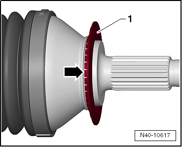
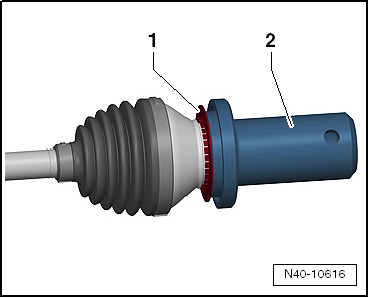
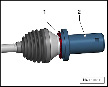
Make sure that deflector disc -1- is fully clipped onto outer CV joint.

Note
- The lugs of deflector disc -1- must point toward outer CV joint.
- Deflector disc -1- must contact the contact surface of outer CV joint -arrow-.

Note
If deflector disc -1- is not positioned correctly or has fallen off outer CV joint, drive it onto outer CV joint up to the stop with pressure piece -T10049-.
- Insert the outer joint into the splines of the wheel hub as far as possible.
- Bolt ball joint to control arm with new nuts -arrows-.
Use new nuts!
Make sure the bellows are undamaged and not twisted.
- Install wheel and tighten.
- Coat the thread and splines of the stub axle and the contact surface between wheel hub and 12-point nut with pressure-resistant oil Fuchs Renolin B15 VG46.
- Tighten the 12-point nut of the driveshaft.

Note
The vehicle must not be standing on its wheels during this step, otherwise the wheel bearing will be damaged.
- Top up the transmission oil.
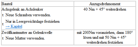
Tightening torques
Disassembling and assembling driveshaft
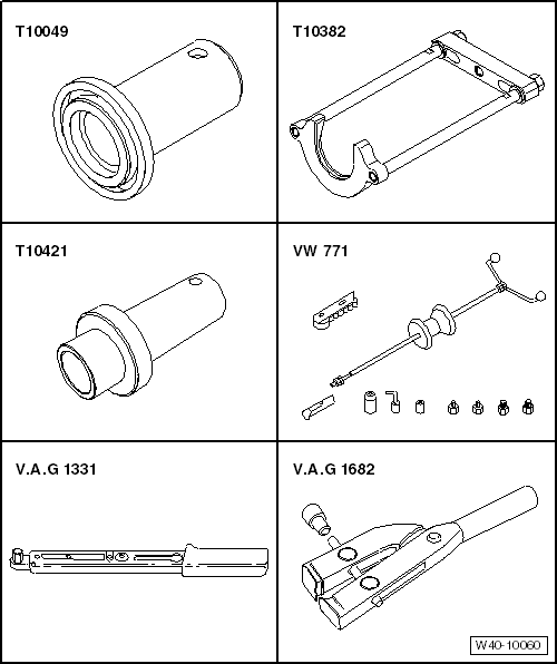
Required Special Tools, Test and Measuring Equipment and Auxiliary Items
- Pressure piece -T10049-
- Puller -T10382-
- Pressure piece -T10421-
- Multi-purpose tool -VW 771-
- Torque Wrench -V.A.G 1331-
- Collet -V.A.G 1682-
- Three-arm puller -Kukko 45-1-
Carry out the following work:
Removing outer constant velocity joint
- Clamp the driveshaft in a vise using protective jaws.
- Open the clamp.
- Turn the boot back.
- Set up puller -T10382- so that the smooth side of puller plate -T10382/1- faces the spindles -T10382/2-.
- Assemble puller -T10382- completely with multi-purpose tool -VW 771-.
- Pull the constant velocity joint off the driveshaft using puller -T10382- and multi-purpose tool -VW 771-.
- Puller plate -T10382/1-
- Spindles -T10382/2-
Installing outer constant velocity joint
- Install a new circlip.
- If necessary, slide a new constant velocity joint boot onto the driveshaft.
- Using a plastic hammer, drive the constant velocity joint onto the shaft until the circlip engages.
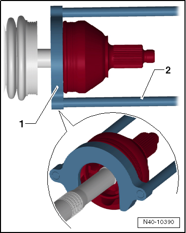
Tensioning new clamp on joint
- Position collet -V.A.G 1682- as shown in the illustration. Make sure the jaws of the collet rest on the corners -arrows B- of the clamp.
- Tension the clamp by turning the spindle with a torque wrench (do not tilt the collet).

Note
- Due to the hard material of the constant velocity joint boot (compared to rubber) and the stainless steel clamp required as a result, this clamp can only be tensioned with collet -V.A.G 1682-.
- Tightening torque: 25 N·m.
- Use torque wrench -C- with a setting range of 5... 50 N·m (e.g. torque wrench -V.A.G 1331-).
- Make sure the thread of spindle -A- of the collet moves smoothly. If necessary, lubricate with MOS 2 grease.
- If the spindle turns stiffly, e.g. due to dirt in the thread, the required clamping force of the clamp will not be reached at the specified tightening torque.
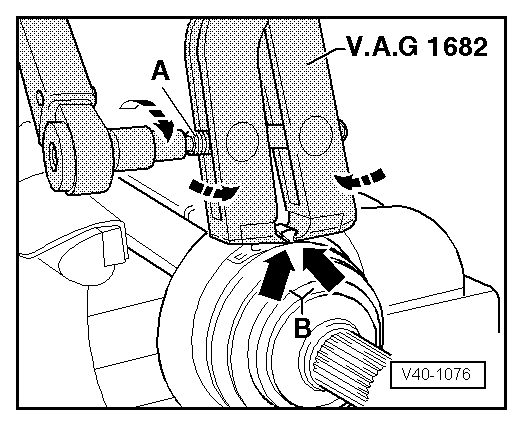
Tensioning new clamp on small diameter
- Position collet -V.A.G 1682- as shown in the illustration. Make sure the jaws of the collet rest on the corners -arrows B- of the clamp.
- Tension the clamp by turning the spindle with a torque wrench (do not tilt the collet).

Note
- Due to the hard material of the constant velocity joint boot (compared to rubber) and the stainless steel clamp required as a result, this clamp can only be tensioned with collet -V.A.G 1682-.
- Tightening torque: 25 N·m.
- Use torque wrench -C- with a setting range of 5... 50 N·m (e.g. torque wrench -V.A.G 1331-).
- Make sure the thread of spindle -A- of the collet moves smoothly. If necessary, lubricate with MOS 2 grease.
- If the spindle turns stiffly, e.g. due to dirt in the thread, the required clamping force of the clamp will not be reached at the specified tightening torque.
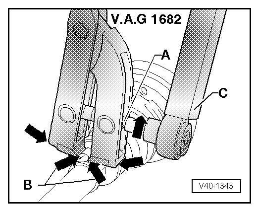
Make sure that deflector disc -1- is fully clipped onto outer CV joint.

Note
- The lugs of deflector disc -1- must point toward outer CV joint.
- Deflector disc -1- must contact the contact surface of outer CV joint -arrow-.

Note
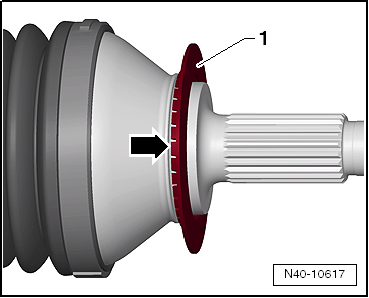
If deflector disc -1- is not positioned correctly or has fallen off outer CV joint, drive it onto outer CV joint up to the stop with pressure piece -T10049-.
Disassembling
- Open both clamps on the inner joint and push back the constant velocity joint boot.
- Remove joint piece from driveshaft.
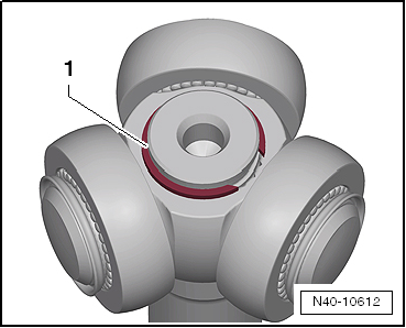
- Remove the circlip -1-.
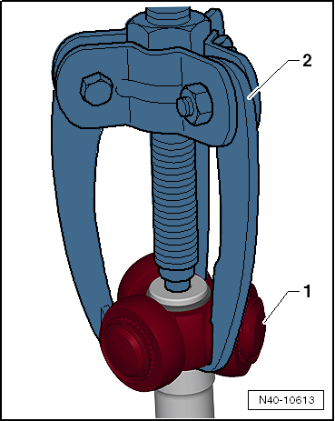
- Pull tripod star -1- off driveshaft using a three-arm puller, e.g. -Kukko 45-1--2-.
- Remove joint boot from shaft.
- Clean shaft, joint piece and groove for sealing ring.
Assembly
- Slide small clamp for joint boot onto shaft.
- Slide joint boot onto shaft.
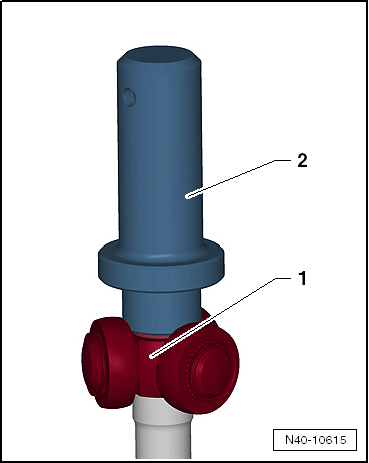
- Place tripod star -1- onto driveshaft -2-.

Note
When fitting, make sure the chamfer -arrow- of tripod star -1- points toward driveshaft -2-.
- Drive tripod star -1- onto driveshaft using pressure piece -T10421--2-.
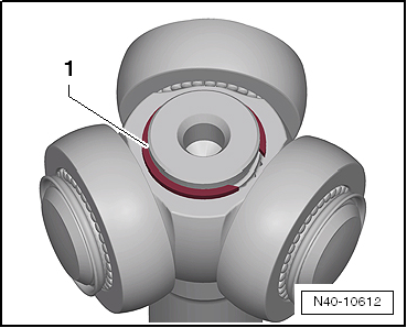
- Insert circlip -1-, making sure it seats correctly.
- Press half of the driveshaft grease from the repair kit into the tripod joint.
- Slide joint piece over the rollers and hold it in place.
- Press the other half of the driveshaft grease from the repair kit into the back of the tripod joint.
- Fit joint boot.
- Tighten clamp on small diameter.
- Tighten clamp on joint piece.
Check outer CV joint
The joint must be disassembled to replace the grease if heavily contaminated, or if the running surfaces of the balls are to be checked for wear and damage.
Carry out the following work:
Removing
- Before disassembly, mark the position of the ball hub relative to the ball cage and housing with an electric marker or scribe.
- Pivot ball hub and ball cage.
- Remove balls one after another.
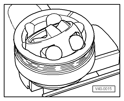
- Turn cage until the 2 rectangular windows -arrow- rest against the joint body.
- Lift out cage with hub.
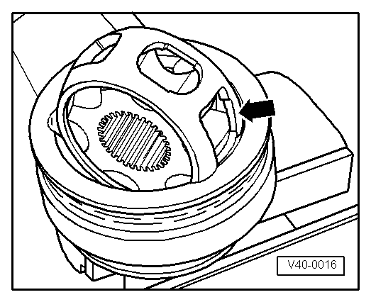
- Pivot segment of hub into rectangular window of cage.
- Tilt hub out of cage.
The 6 balls of each joint belong to one tolerance group. Check stub axle, hub, cage and balls for small pits (pitting) and galling. Excessive rotational play in the joint is noticeable as knocking under load changes. In such cases, the joint must be replaced. Smoothing and running marks on the balls are not a reason to replace the joint.
Installing
- Press half of the total grease quantity (40 grams) into joint body.
- Insert cage with hub into joint body.
- Press opposite balls in one after another, making sure the original position of the ball hub relative to the ball cage and joint body is restored.
- Insert new circlip into hub.
- Distribute remaining grease quantity in joint boot.