Strut, upper control arm
Assembly overview - strut, upper control arm

Note
- Welding and straightening work on load-bearing and wheel-guiding components of the wheel suspension is not permitted.
- Always replace self-locking nuts.
- Always replace corroded bolts/nuts.
- Rubber-metal bearings have a limited rotation range. Therefore, only tighten the bolted connections on components with rubber-metal bearings once the wheel bearing housing is raised (unladen position).
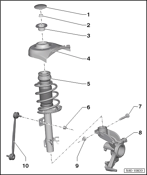
- Cap
- Assignment → Electronic Parts Catalog "ETKA"
- Nut
- 60 N·m
- replace after every removal
- Stop
- Body front
- Strut
- Remove and install
- Nut
- 40 N·m
- Self-locking
- replace after every removal
- Internal Torx bolt
- Tip of bolt must point in direction of travel
- Wheel bearing housing
- Remove and install
- If wheel bearing housing is replaced, vehicle must be measured afterward
- different versions
- Assignment → Electronic Parts Catalog "ETKA"
- Nut
- 70 N·m + continue turning 90º
- replace after every removal
- Stabilizer link
Remove and install strut
Required Special Tools, Test and Measuring Equipment and Auxiliary Items
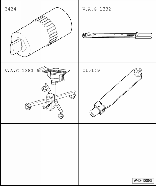
- Torque Wrench -V.A.G 1332-
- Spreader -3424-
- Engine and Transmission Hoist -V.A.G 1383 A-
- Support -T10149-
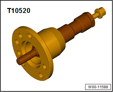
- Ejector -T10520-
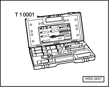
- Shock absorber set -T10001-
Carry out the following work:
Removing
- Raise vehicle until front axle is relieved of load.
- Loosen 12-point nut for driveshaft.

Caution!
If wheel-side driveshaft bolt connection is loose, wheel bearings must not be loaded.
If the wheel bearings are loaded by the weight of the vehicle, they will be pre-damaged. This reduces the service life of the wheel bearings.
The bolt for the driveshaft may be loosened by a maximum of 90º if the vehicle is standing on its wheels.
Vehicles without driveshaft must not be moved, otherwise the wheel bearing will be damaged. If a vehicle must nevertheless be moved, observe the following:
- Install an outer CV joint instead of the driveshaft.
- Tighten outer CV joint to 120 N·m.
- Loosen wheel bolts.
- Raise the vehicle.
- Remove wheel.
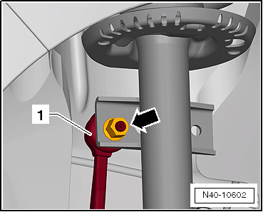
- Unscrew nut -arrow- and pull coupling rod -1- out of strut.
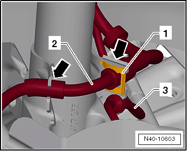
- Remove retaining spring for brake line -1- and unhook brake line -2- from strut -arrows-.
- Disconnect connector from ABS wheel speed sensor.
- Disconnect wheel speed sensor wire -3- from strut.
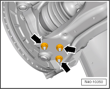
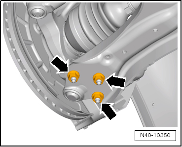
- Unscrew nuts -arrows-.
- Pull control arm out of ball joint.
- Pull outer CV joint of driveshaft out of wheel hub.
If the driveshaft cannot be pulled out of the wheel bearing, press the driveshaft out of the wheel bearing with puller -T10520-.
Before using puller -T10520-, make sure that pressure piece -1- is installed.
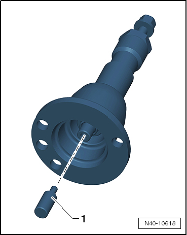
Using puller -T10520-:
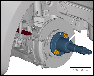
- Attach puller -T10520--1- to wheel hub with 2 wheel bolts.
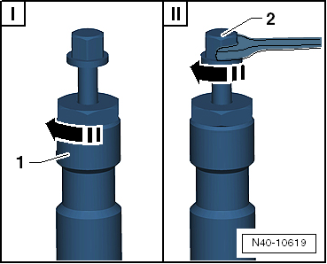
- Be sure to observe the specified sequence.
- Tighten knurled nut -1- by hand.
- Turn only bolt -2- with a wrench and press driveshaft out using puller -T10520-.

Note
At the end of the procedure, or before retightening, return the spindle to its starting position so the hydraulic action can be used!
- Secure driveshaft to body with binding wire.
- Bolt ball joint back to control arm.
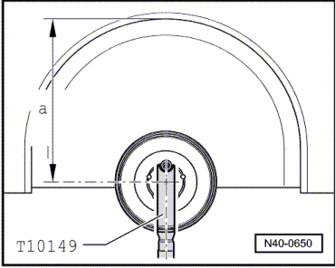
- Attach engine and transmission jack -V.A.G 1383 A- with holder -T10149- to wheel hub using one wheel bolt.

WARNING!
- Do not raise or lower the vehicle while the engine and transmission jack -V.A.G 1383 A- is under the vehicle. The vehicle could slip off the lift.
- Do not leave the engine and transmission jack under the vehicle longer than necessary.
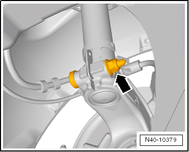
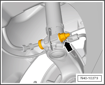
- Remove bolted connection between wheel bearing housing and strut -arrow-.
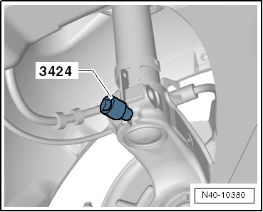
- Insert spreader -3424- into slot of wheel bearing housing.
- Turn ratchet 90° and pull it off spreader -3424-.
- Press brake disc by hand in direction of strut.
Otherwise the shock absorber tube may jam in the bore of the wheel bearing housing.
- Pull wheel bearing housing down off shock absorber tube and lower it with engine and transmission jack -V.A.G 1383 A- until shock absorber tube hangs freely.
- Secure wheel bearing housing to subframe.
- Remove holder -T10149- from wheel hub and remove engine and transmission jack -V.A.G 1383 A- from under vehicle.

WARNING!
Do not leave the engine and transmission jack under the vehicle longer than necessary.
- Remove cowl panel cover, refer to Body Assembly Work Exterior.
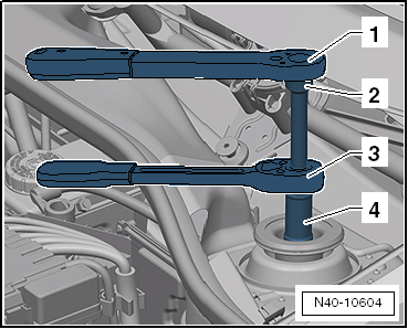
- Unscrew upper shock absorber mounting and remove strut downward.
- Ratchet, commercially available
- -T10001/8-
- -T10001/11-
- -T10001/5-
Installing
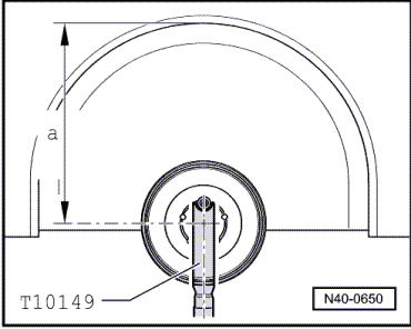
- Attach engine and transmission jack -V.A.G 1383 A- with holder -T10149- to wheel hub using one wheel bolt.
- Attach strut to wheel bearing housing and secure with internal splined bolt and a new nut.
The tip of the internal splined bolt must point in the direction of travel.
- Remove spreader -3424-.
- Carefully raise wheel bearing housing with engine and transmission jack until strut rests against inside of strut tower.
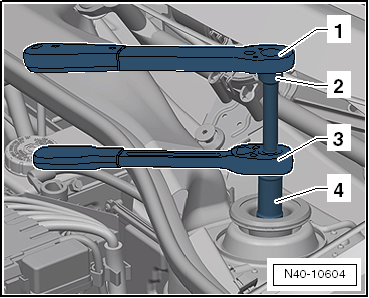
- Place stop on strut tower and tighten nut for upper shock absorber mounting to specified tightening torque.
- Torque Wrench -V.A.G 1332-
- -T10001/8-
- -T10001/11-
- -T10001/5-
- Remove holder -T10149- from wheel hub and remove engine and transmission jack -V.A.G 1383 A- from under vehicle.

WARNING!
Do not leave the engine and transmission jack under the vehicle longer than necessary.
- Tighten bolted connection between wheel bearing housing and strut -arrow-.
- Unscrew nuts -arrows-.
- Pull control arm out of ball joint.
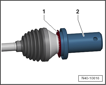
Make sure that deflector disc -1- is fully clipped onto outer CV joint.

Note
- The lugs of deflector disc -1- must point toward outer CV joint.
- Deflector disc -1- must contact the contact surface of outer CV joint -arrow-.

Note
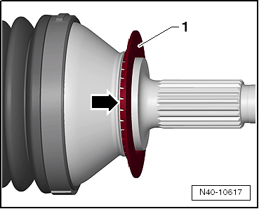
If deflector disc -1- is not positioned correctly or has fallen off outer CV joint, drive it onto outer CV joint up to the stop with pressure piece -T10049-.
- Insert driveshaft into wheel bearing.
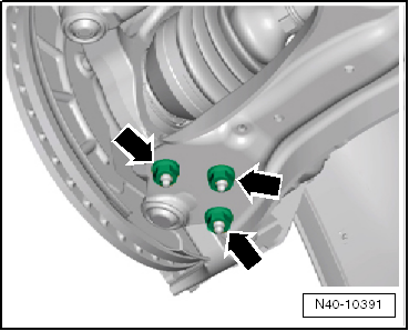
- Bolt ball joint to control arm with new nuts -arrows-.
Use new nuts!
Make sure the bellows are undamaged and not twisted.
Installation is carried out in reverse order.
- Install cowl cover → Body Assembly Work, Exterior.
- Install wheel and tighten.
- Tighten 12-point nut for driveshaft.

Note
The vehicle must not be standing on its wheels during this step, otherwise the wheel bearing will be damaged.
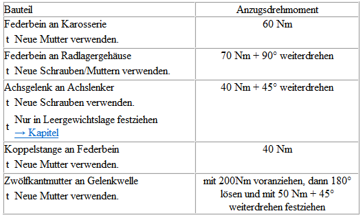
Tightening torques
Repair strut
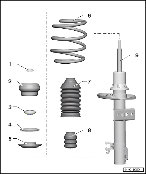
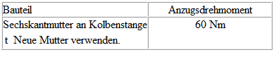
- Nut
- 60 N·m
- Self-locking
- replace after every removal
- Strut mount
- Observe installation position.
- Thrust bearing
- Spacer
- Assignment → Electronic Parts Catalog "ETKA"
- Spring plate
- Spring
- Remove and install
- Observe color coding
- Assignment → Electronic Parts Catalog "ETKA"
Spring assignment is made using the PR number. The PR number is shown on the vehicle data plate.
Surface of spring coil must not be damaged- Protective cover
- Bump stop
- Damper
- individually replaceable
- Assignment → Electronic Parts Catalog "ETKA"
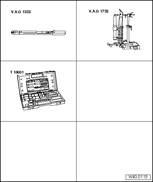
Required Special Tools, Test and Measuring Equipment and Auxiliary Items
- Torque Wrench -V.A.G 1332-
- Spring compressor for struts -V.A.G 1752-
- Coil spring compressor -V.A.G 1752/1-
- Spring holder -V.A.G 1752/7-
- Shock absorber set -T10001-
Carry out the following work:
- Remove strut.
Remove spring
- Clamp strut spring compressor stand -V.A.G 1752/20--4- in a vise.
- Clamp strut in strut spring compressor stand -V.A.G 1752/20-.
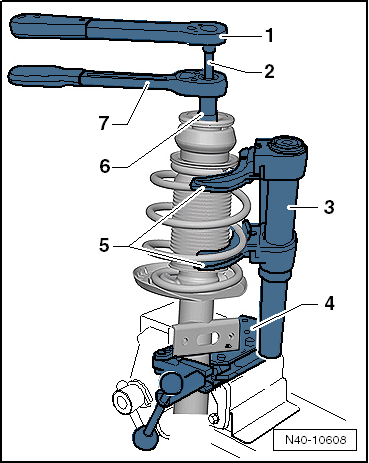
- Compress spring with coil spring compressor -V.A.G 1752/1- until thrust bearing at top is free.
- Torque Wrench -V.A.G 1332-
- Socket insert -T10001/8-
- Coil spring compressor -V.A.G 1752/1-
- Strut spring compressor stand -V.A.G 1752/20-
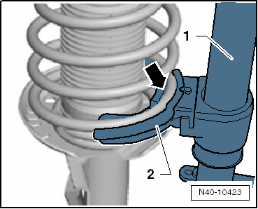
- Spring holder -V.A.G 1752/4-
- Socket insert -T10001/5-
- Ratchet -T10001/11-

WARNING!
First compress the spring until the upper spring plate is relieved!
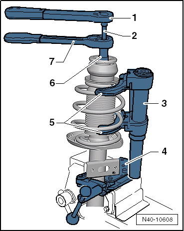
- Make sure spring is correctly seated in spring holder -V.A.G 1752/4--arrow-.
- Coil spring compressor -V.A.G 1752/1-
- Spring holder -V.A.G 1752/7-
- Unscrew hex nut from piston rod.
- Remove individual strut components and spring using spring compressor for struts -V.A.G 1752-.
Install spring
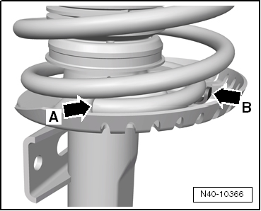
- Place spring on lower spring seat using spring compressor for struts -V.A.G 1752-.
The end of the spring coil must rest against stop -arrow A- and against lug -arrow B-.
- Place spring plate, thrust bearing and strut mount onto spring.
The collar of the strut mount -arrow- must face the spring plate.
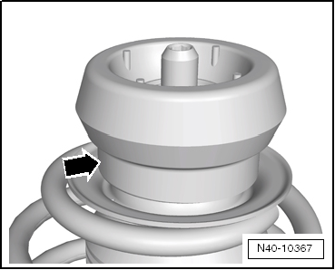
- Tighten new hex nut on piston rod.
- Torque Wrench -V.A.G 1332-
- Socket insert -T10001/8-
- Coil spring compressor -V.A.G 1752/1-
- Strut spring compressor stand -V.A.G 1752/20-
- Spring holder -V.A.G 1752/4-
- Socket insert -T10001/5-
- Ratchet -T10001/11-
- Release spring compressor for struts -V.A.G 1752- and remove it from spring.
- Install strut.
Tightening torque