Brake booster/Master cylinder
Removing and installing brake booster
Removing and installing brake booster, left-hand drive
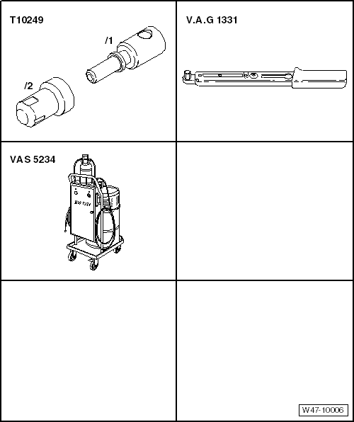
Required Special Tools, Test and Measuring Equipment and Auxiliary Items
- Sealing plug tool -T10249-
- Torque Wrench -V.A.G 1331-
- Brake filling and bleeding unit -VAS 5234-
Removing:
- On vehicles with coded radio, observe the radio coding; ask the customer if necessary.
- Remove the battery → Electrical System.
- Remove the engine control module with bracket and set it aside → 3-cyl. injection engine, toothed belt drive (4-valve).
- Remove the battery tray → Electrical system.
- Remove the air filter housing → 3-cyl. injection engine, toothed belt drive (4-valve).
- Lay out enough lint-free rags in the area of the engine and the transmission.
- Extract as much brake fluid as possible from the brake fluid reservoir with the brake filling and bleeding unit -VAS 5234-.
Only on vehicles with air conditioning:
- Disconnect the connector -2- from the high-pressure sensor -G65--1-.
Continued for all vehicles:
- Disconnect the connector -A- from the brake fluid level warning contact -F34-.
- Disconnect the connector -B- from the brake light switch -F-.
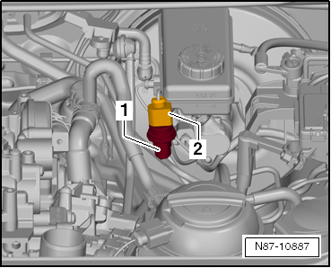
- Then unclip the wiring harness from the brake master cylinder.
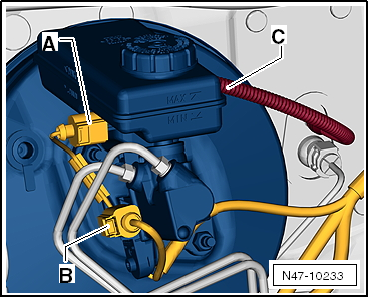
- Disconnect the clutch master cylinder compensating hose -C- from the brake fluid reservoir.
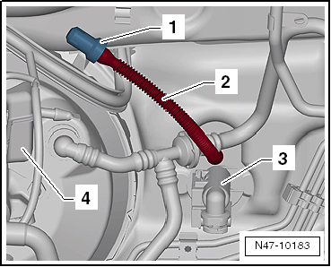
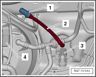
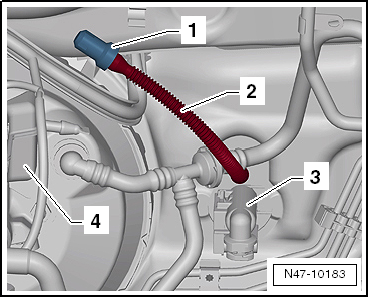
- Seal the clutch master cylinder compensating hose -2- -3- with plug tool -T10249--1- or engine plug set -VAS 6122-.
- Tie up the compensating hose -2-.
- Pull the vacuum hose off the brake booster.
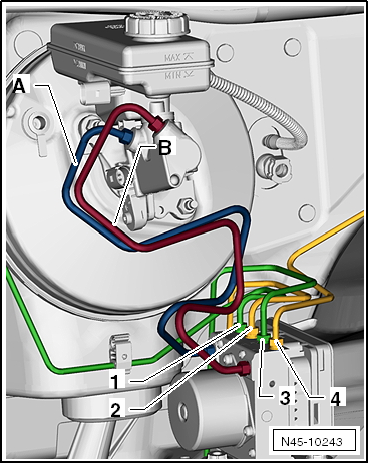
- Mark the brake lines on the brake master cylinder -A and B-, unscrew them and immediately seal them with the plugs from repair kit ET no. 1H0 698 311 A.
- Then loosen the brake lines -A and B- slightly at the hydraulic unit and move them aside.
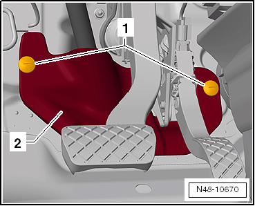
- Unscrew bolts -1- and remove footwell trim -2-.
- Separate the brake pedal from the brake booster.
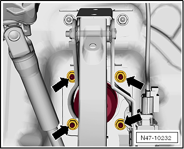
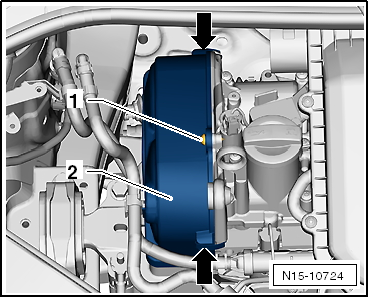
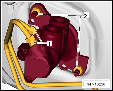
- Unscrew the hex nuts -arrows-.
- Carefully remove the brake booster from the vehicle.
- If the brake booster is jammed in the holes, loosen the two remaining nuts from the bearing bracket.
- Unscrew the brake master cylinder from the brake booster.
- Carefully remove the brake master cylinder from the brake booster.
Installing:
- Installation is carried out in the reverse order.
When installing, observe the following points:
- Clip the brake pedal onto the brake booster.
- Bleed the brake system.
Tightening torques:
Brake booster to pedal cluster/bulkhead - 25 N·m
- Use new nuts!
Brake master cylinder to brake booster - 23 N·m
- Use new nuts!
Brake lines to brake master cylinder - 14 N·m
Removing and installing brake booster, right-hand drive
- Remove the air filter housing → 3-cyl. injection engine, toothed belt drive (4-valve).
- Clip the fuel supply line -1- and the vent line -2- out of the holder.
- Unhook the clips of the timing belt cover -arrows-.
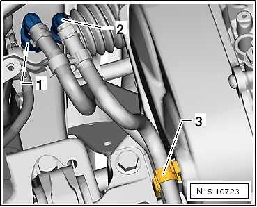
- Unscrew the fastening bolt -1- and remove the timing belt cover -2-.
- Lay out sufficient lint-free cloths in the adjacent area.
- Extract as much brake fluid as possible from the brake fluid reservoir with the brake filling and bleeding unit -VAS 5234-.
- Disconnect the connector -A- from the brake fluid level warning contact -F34-.
- Disconnect the connector -B- from the brake light switch -F-.
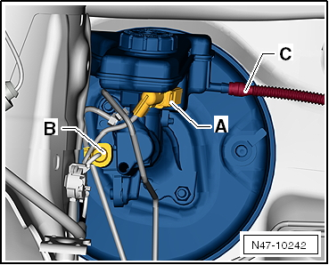
- Disconnect the clutch master cylinder compensating hose -C- from the brake fluid reservoir.
- Seal the clutch master cylinder compensating hose -2- -3- with plug tool -T10249--1- or engine plug set -VAS 6122-.
- Tie up the compensating hose -2-.
- Pull the vacuum hose off the brake booster.
- Unscrew the Torx bolt -1- from the mounting lugs of the brake fluid reservoir and the brake master cylinder.
- Pull the brake fluid reservoir -2- upward -arrow- out of the brake master cylinder.
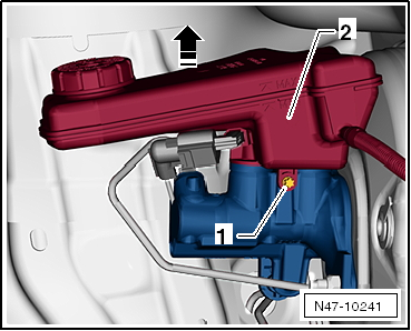
- Mark the brake lines on the brake master cylinder -1-, then unscrew them.
- Unscrew the nuts -2- from the brake master cylinder.
- Carefully remove the brake master cylinder from the brake booster.
- Separate the brake pedal from the brake booster.
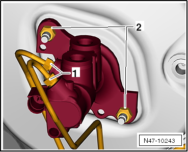
- Unscrew the hex nuts -arrows-.
- Remove the cowl panel cover. Refer to Body Assembly Work Exterior.
- Remove the bulkhead. Refer to Body Assembly Work Exterior.
- Carefully pull the brake booster out of the holes.
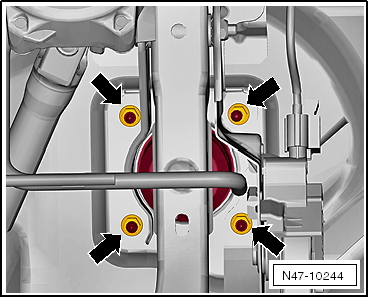
- If the brake booster is jammed in the holes, loosen the two remaining nuts from the bearing bracket.
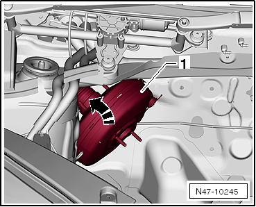
- Then rotate the brake booster -1- and push it in the direction of the arrow, push rod first, into the corner under the cowl panel.
- Now remove the brake booster upward.
Installing:
- Installation is carried out in the reverse order.
When installing, observe the following points in particular:
- Clip the brake pedal onto the brake booster.
- When assembling the brake master cylinder to the brake booster, make sure the push rod is correctly seated in the brake master cylinder and that the sealing ring is in place.
- Bleed the brake system.
Tightening torques:
Brake booster to pedal cluster/bulkhead - 25 N·m
- Use new nuts!
Brake master cylinder to brake booster - 23 N·m
- Use new nuts!
Brake lines to brake master cylinder - 14 N·m
Removing and installing brake master cylinder
Removing and installing brake master cylinder, left-hand drive
Required Special Tools, Test and Measuring Equipment and Auxiliary Items
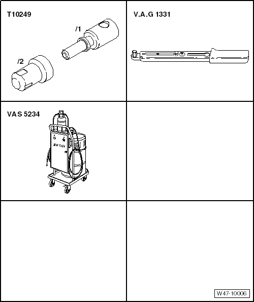
- Sealing plug tool -T10249-
- Torque Wrench -V.A.G 1331-
- Brake filling and bleeding unit -VAS 5234-
Removing:
- On vehicles with coded radio, observe the radio coding; ask the customer if necessary.
- Remove the battery → Electrical System.
- Remove the air filter housing → 3-cyl. injection engine, toothed belt drive (4-valve).
- Lay out enough lint-free rags in the area of the engine and the transmission.
- Extract as much brake fluid as possible from the brake fluid reservoir with the brake filling and bleeding unit -VAS 5234-.
Only on vehicles with air conditioning:
- Disconnect the connector -2- from the high-pressure sensor -G65--1-.
Continued for all vehicles:
- Disconnect the connector -A- from the brake fluid level warning contact -F34-.
- Disconnect the connector -B- from the brake light switch -F-.
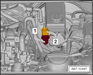
- Then unclip the wiring harness from the brake master cylinder.
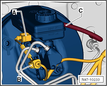
- Disconnect the clutch master cylinder compensating hose -C- from the brake fluid reservoir.
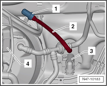
- Seal the clutch master cylinder compensating hose -2- -3- with plug tool -T10249--1- or engine plug set -VAS 6122-.
- Tie up the compensating hose -2-.
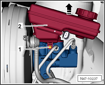
- Unscrew the Torx bolt -1- from the mounting lugs of the brake fluid reservoir and the brake master cylinder.
- Pull the brake fluid reservoir -2- upward -arrow- out of the brake master cylinder.
- Mark the brake lines on the brake master cylinder -1-, then unscrew them.
- Unscrew the nuts -2- from the brake master cylinder.
- Carefully remove the brake master cylinder from the brake booster.
- Remove the brake light switch -F-.
Installing:
- Installation is carried out in the reverse order.
When installing, observe the following points in particular:
- When assembling the brake master cylinder to the brake booster, make sure the push rod is correctly seated in the brake master cylinder and that the sealing ring is in place.
- Bleed the brake system.
Tightening torques:
Brake master cylinder to brake booster - 23 N·m
- Use new nuts!
Brake lines to brake master cylinder - 14 N·m
Torx bolt for brake fluid reservoir - 8 N·m
Torx bolt for brake light switch on brake master cylinder - 7 N·m
Removing and installing brake master cylinder, right-hand drive
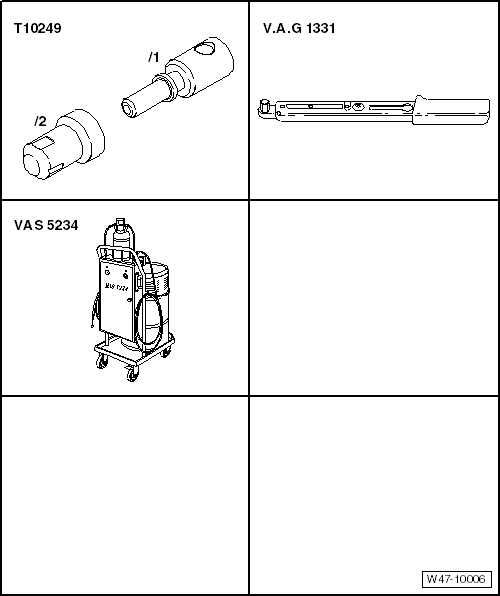
Required Special Tools, Test and Measuring Equipment and Auxiliary Items
- Sealing plug tool -T10249-
- Torque Wrench -V.A.G 1331-
- Brake filling and bleeding unit -VAS 5234-
Removing:
- Remove the air filter housing → 3-cyl. injection engine, toothed belt drive (4-valve).
- Lay out sufficient lint-free cloths in the adjacent area.
- Extract as much brake fluid as possible from the brake fluid reservoir with the brake filling and bleeding unit -VAS 5234-.
- Disconnect the connector -A- from the brake fluid level warning contact -F34-.
- Disconnect the connector -B- from the brake light switch -F-.
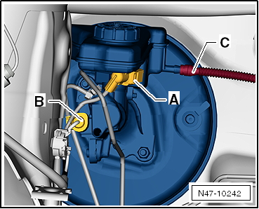
- Disconnect the clutch master cylinder compensating hose -C- from the brake fluid reservoir.
- Seal the clutch master cylinder compensating hose -2- -3- with plug tool -T10249--1- or engine plug set -VAS 6122-.
- Tie up the compensating hose -2-.
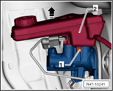
- Unscrew the Torx bolt -1- from the mounting lugs of the brake fluid reservoir and the brake master cylinder.
- Pull the brake fluid reservoir -2- upward -arrow- out of the brake master cylinder.
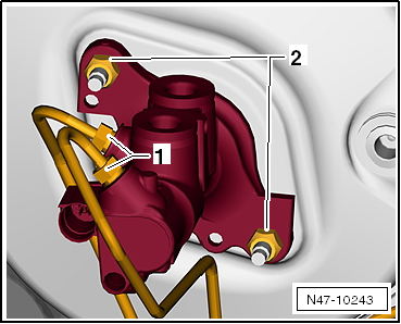
- Mark the brake lines on the brake master cylinder -1-, then unscrew them.
- Unscrew the nuts -2- from the brake master cylinder.
- Carefully remove the brake master cylinder from the brake booster.
- Remove the brake light switch -F-.
Installing:
- Installation is carried out in the reverse order.
When installing, observe the following points in particular:
- When assembling the brake master cylinder to the brake booster, make sure the push rod is correctly seated in the brake master cylinder and that the sealing ring is in place.
- Bleed the brake system.
Tightening torques:
Brake master cylinder to brake booster - 23 N·m
- Use new nuts!
Brake lines to brake master cylinder - 14 N·m
Torx bolt for brake fluid reservoir - 8 N·m
Torx bolt for brake light switch on brake master cylinder - 7 N·m
Removing and installing brake light switch
Removing and installing brake light switch, left-hand drive
Required Special Tools, Test and Measuring Equipment and Auxiliary Items
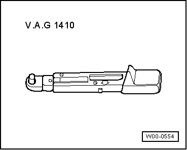
- Torque wrench -V.A.G 1410-
Removing:
- Remove the air filter housing → 3-cyl. injection engine, toothed belt drive (4-valve).
Only on vehicles with air conditioning:
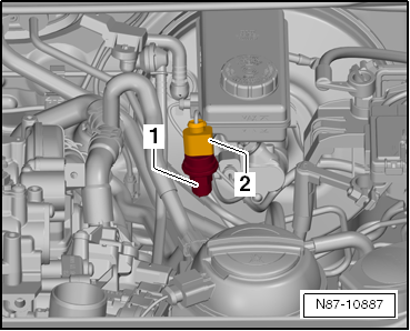
- Disconnect the connector -2- from the high-pressure sensor -G65--1-.
Continued for all vehicles:
- Disconnect the connector -A- from the brake fluid level warning contact -F34-.
- Disconnect the connector -B- from the brake light switch -F-.
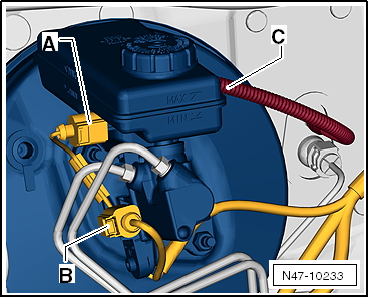
- Move the connectors with the wiring harness aside.
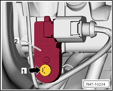
- Unscrew the screw -1 arrow- from the brake master cylinder.
- Pull the brake light switch -F- -2- off the brake master cylinder.
Installing:
- Installation is carried out in the reverse order.
Tightening torque:
Torx bolt on brake master cylinder - 7 N·m
Removing and installing brake light switch, right-hand drive
Required Special Tools, Test and Measuring Equipment and Auxiliary Items
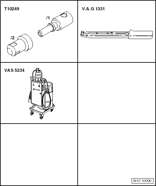
- Sealing plug tool -T10249-
- Torque Wrench -V.A.G 1331-
- Brake filling and bleeding unit -VAS 5234-
Removing:
- Remove the air filter housing → 3-cyl. injection engine, toothed belt drive (4-valve).
- Lay out sufficient lint-free cloths in the adjacent area.
- Extract as much brake fluid as possible from the brake fluid reservoir with the brake filling and bleeding unit -VAS 5234-.
- Disconnect the connector -A- from the brake fluid level warning contact -F34-.
- Disconnect the connector -B- from the brake light switch -F-.
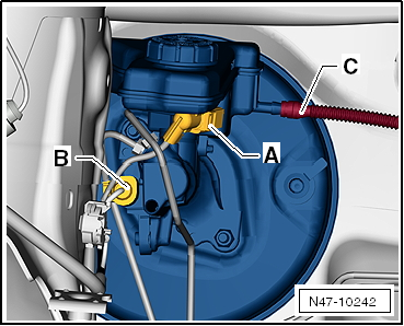
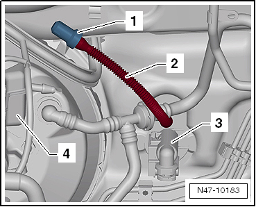
- Disconnect the clutch master cylinder compensating hose -C- from the brake fluid reservoir.
- Seal the clutch master cylinder compensating hose -2- -3- with plug tool -T10249--1- or engine plug set -VAS 6122-.
- Tie up the compensating hose -2-.
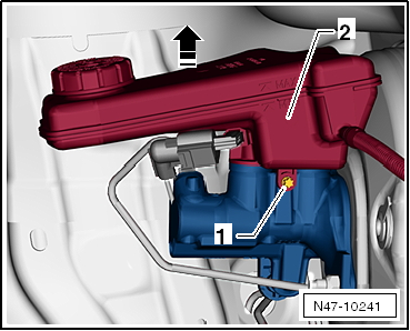
- Unscrew the Torx bolt -1- from the mounting lugs of the brake fluid reservoir and the brake master cylinder.
- Pull the brake fluid reservoir -2- upward -arrow- out of the brake master cylinder.
- Move the connectors with the wiring harness aside.
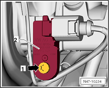
- Unscrew the screw -1 arrow- from the brake master cylinder.
- Pull the brake light switch -F- -2- off the brake master cylinder.
Installing:
- Installation is carried out in the reverse order.
- Bleed the brake system.
Tightening torque:
Torx bolt on brake master cylinder - 7 N·m
Assembly overview - brake booster/brake master cylinder
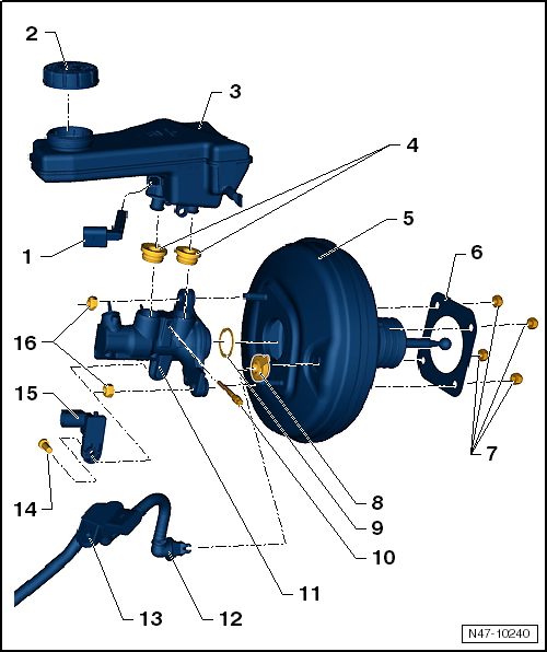
Assembly overview - brake booster/brake master cylinder, left-hand drive
The complete brake master cylinder and brake booster can be replaced independently of each other.
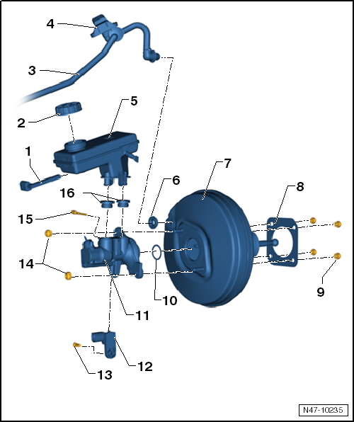
- Brake fluid level warning contact -F34-
- Filler Cap
- Vacuum hose
- including check valve
- Pressure sensor
- only on vehicles with start/stop system
- Brake fluid reservoir
- Sealing plug
- Brake booster
- On petrol engines, the required vacuum is taken from the intake manifold.
- Function check
- With the engine off, depress the brake pedal firmly several times (this releases the vacuum stored in the unit).
- Now hold the brake pedal in the applied position with moderate foot force and start the engine. If the brake booster is working properly, the brake pedal will noticeably give way under the foot (boost takes effect).
If faulty, replace completely; first check the vacuum system for the brake booster. Non-return valve (in vacuum hose); functional test: disconnect from brake pedal. Remove and install- Gasket
- for brake booster
- Hex nut, self-locking, 25 N·m
- replace after every removal.
- Sealing ring
- Replace
- Brake master cylinder
- cannot be repaired. If faults occur, replace the complete unit.
- Brake light switch -F-
- including brake pedal switch -F47-
- Remove and install
- Torx bolt, 7 N·m
- Hex nut, self-locking, 23 N·m
- replace after every removal.
- Torx bolt, 8 N·m
- Sealing plug
- Wet with brake fluid and press into the brake master cylinder.
Assembly overview - brake booster/brake master cylinder, right-hand drive
The complete brake master cylinder and brake booster can be replaced independently of each other.
- Brake fluid level warning contact -F34-
- Filler Cap
- Brake fluid reservoir
- Sealing plug
- Wet with brake fluid and press into the brake master cylinder.
- Brake booster
- On petrol engines, the required vacuum is taken from the intake manifold.
- Function check
- With the engine off, depress the brake pedal firmly several times (this releases the vacuum stored in the unit).
- Now hold the brake pedal in the applied position with moderate foot force and start the engine. If the brake booster is working properly, the brake pedal will noticeably give way under the foot (boost takes effect).
If faulty, replace completely; first check the vacuum system for the brake booster. Non-return valve (in vacuum hose); functional test: disconnect from brake pedal. Remove and install- Gasket
- for brake booster
- Hex nut, self-locking, 25 N·m
- replace after every removal.
- Sealing plug
- Sealing ring
- Replace
- Torx bolt, 8 N·m
- Brake master cylinder
- cannot be repaired. If faults occur, replace the complete unit.
- Vacuum hose
- including check valve
- Pressure sensor
- only on vehicles with start/stop system
- Torx bolt, 7 N·m
- Brake light switch -F-
- including brake pedal switch -F47-
- Remove and install
- Hex nut, self-locking, 23 N·m
- replace after every removal.