Headliners
Installation location overview - headliner

Note
The illustration shows the headliner for vehicles without panoramic sliding roof. The headliner for vehicles with panoramic sliding roof is similar.
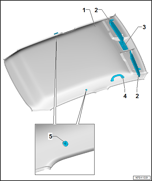
- Molded headliner
- without panoramic sliding roof
- Assembly Overview
- Remove and install

Caution!
The molded headliner is very sensitive to kinks.
- Sun visor
- Remove and install
- Front interior and reading light
- Remove and install
- Grab handle
- Remove and install
- Hole for partition bracket
- load up! only
Exploded view of molded headliner

Note
The illustration shows the molded headliner for vehicles with panoramic sliding roof. The molded headliner for vehicles without panoramic sliding roof is similar.
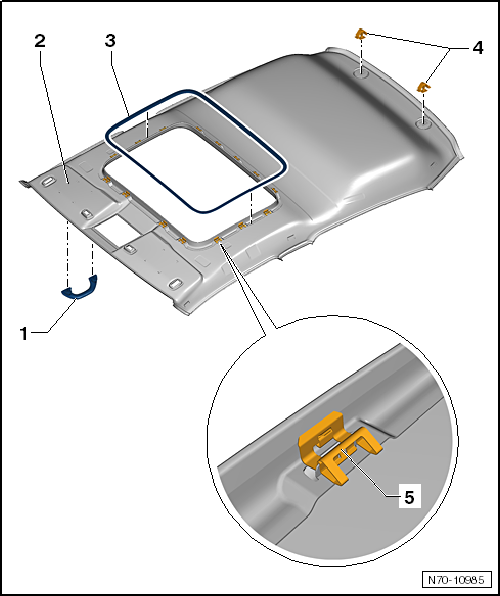
- Grab handle
- Remove and install
- Molded headliner
- with or without panoramic sliding roof (depending on equipment)
- Remove and install

Caution!
The molded headliner is very sensitive to kinks.
- Frame surround
- only on vehicles with panoramic sliding roof
- Observe installation position: yellow marking on frame surround must point in direction of travel
- Clip
- 2 pieces
- insert into molded headliner
- remove clips remaining in body mounting points and insert them into molded headliner for installation
- replace damaged or deformed clips
- Clip
- 15 pcs.
- replace damaged or deformed brackets
Removing and installing molded headliner
Removing and installing molded headliner, vehicles without panoramic sliding roof

Note
The molded headliner for load up! must be fitted at the partition bracket.
Required Special Tools, Test and Measuring Equipment and Auxiliary Items
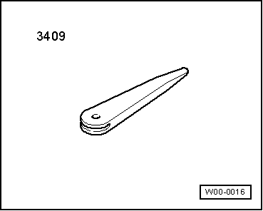
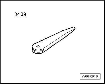
- Release Wedge -3409-
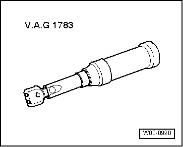
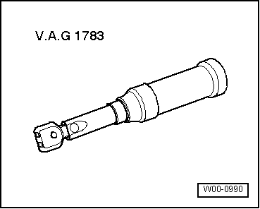
- Torque wrench -V.A.G 1783-
Removing
- Remove interior mirror.
- Remove front interior and reading light → Electrical System.
- Remove sun visors on left and right.
- Remove center bracket for sun visor on left and right.
- Remove grab handle.
- Remove upper A-pillar trim on left and right.
2-door
- Remove B-pillar trim, left and right.
- Remove C-pillar trim on left and right.
4-door
- Release B-pillar trim on left and right.

Note
The safety belt does not need to be threaded through the opening in the B-pillar trim.
- Remove upper C-pillar trim on left and right.
- Remove rear seat backrest.
- Remove tailgate seal → Body Assembly Work Exterior.
load-up!
- Remove load floor.
- Remove partition.
Continuation for all vehicles
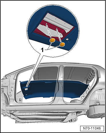
- Unscrew bolts -1- (2 N·m).

Caution!
The molded headliner is very sensitive to kinks.
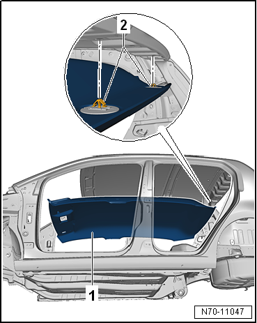
- Release headliner -1- from rear roof cross member at clips -2- using removal wedge -3409-.
- Fold front seat backrests rearward.
- Release headliner -1- from the beads of the door seals.
- Release headliner -1- from the bead of the tailgate seal.

Note
A second technician is required to remove the headliner.
- Lower headliner -1- with a second technician.
2-door
- Carefully remove headliner -1- through the passenger-side door opening with a second technician.
4-door
- Headliner -1- carefully remove with a second technician through the tailgate opening.
Installing

Note
- Before installation, check all fasteners for damage and replace them if necessary.
- Always replace clips -2- before installation.
- Installation is performed in the reverse order.
Removing and installing headliner, vehicles with panoramic tilt/slide sunroof
Required Special Tools, Test and Measuring Equipment and Auxiliary Items
- Release Wedge -3409-
- Torque wrench -V.A.G 1783-
Removing
- Open the panoramic tilt/slide sunroof.
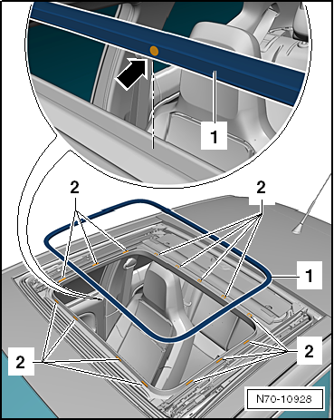
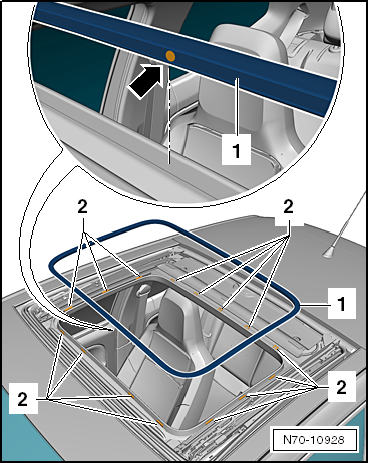
- Release frame -1- of the panoramic tilt/slide sunroof from clips -2- with removal wedge -3409- and remove.
- Remove interior mirror.
- Remove front interior and reading light → Electrical System.
- Remove sun visors on left and right.
- Remove center bracket for sun visor on left and right.
- Remove grab handle.
- Remove upper A-pillar trim on left and right.
2-door
- Remove B-pillar trim, left and right.
- Remove C-pillar trim on left and right.
4-door
- Release B-pillar trim on left and right.

Note
The safety belt does not need to be threaded through the opening in the B-pillar trim.
- Remove upper C-pillar trim on left and right.
- Remove rear seat backrest.
- Remove tailgate seal → Body Assembly Work Exterior.
Continuation for all vehicles
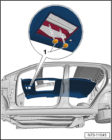
- Unscrew bolts -1- (2 N·m).

Caution!
The molded headliner is very sensitive to kinks.
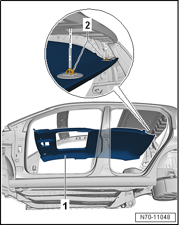
- Release headliner -1- from rear roof cross member at clips -2- using removal wedge -3409-.
- Fold front seat backrests rearward.
- Release headliner -1- from the beads of the door seals.
- Release headliner -1- from the bead of the tailgate seal.

Note
A second technician is required to remove the headliner.
- Lower headliner -1- with a second technician.
2-door
- Carefully remove headliner -1- through the passenger-side door opening with a second technician.
4-door
- Headliner -1- carefully remove with a second technician through the tailgate opening.
Installing

Note
- Before installation, check all fasteners for damage and replace them if necessary.
- Always replace clips -2- before installation.
Installation is carried out in the reverse order of removal, observing the following:

Note
Yellow marking -arrow- on frame -1- must point in the direction of travel.
- Attach frame -1- of the panoramic tilt/slide sunroof to clips -2- on the headliner.
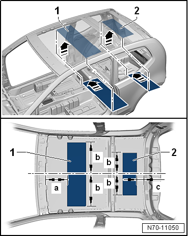
Installing roof reinforcements on body
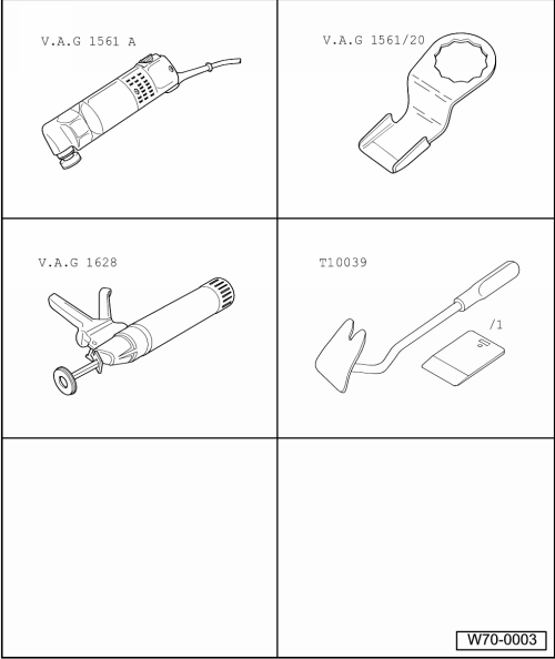
Required Special Tools, Test and Measuring Equipment and Auxiliary Items
- Electric knife -V.A.G 1561 A-
- Cutting knife -V.A.G 1561/20-
- Hand pressure gun -V.A.G 1628-
- Release lever -T10039-
Removing
- Remove headliner.
- Cut roof reinforcements -1- and -2- into approx. 6 cm wide strips -3- with a utility knife -dashed lines-.
- Peel strips -3- off the roof.
- Trim off adhesive residue with electric cutter -V.A.G 1561 A- and cutting knife -V.A.G 1561/20-.

Note
If the paint build-up was damaged when removing the roof reinforcements, repair the paint damage according to the specifications in the → Paint repair manual.
Installing

Note
When installing the roof reinforcements, observe the processing instructions of the adhesive.
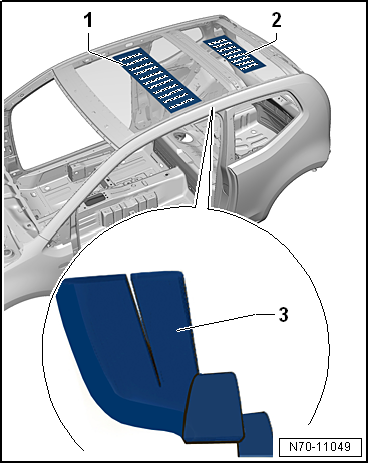
- Measure the width of roof reinforcements -1- and -2- and mark the center on both sides.
- Feed roof reinforcements -1- into the vehicle.
- Position roof reinforcements -1- on the roof according to -dimension a- and -dimension b- and press on over the entire surface.
- Dimension a = 370 mm from front sheet metal edge
- Dimension b = center of roof and center of roof reinforcements
- Feed roof reinforcements -2- into the vehicle.
- Position roof reinforcements -2- on the roof according to -dimension a- and -dimension b- and press on over the entire surface.
- Vehicles without panoramic tilt/slide sunroof
- Dimension b = center of roof and center of roof reinforcements
- Dimension c = 120 mm from rear sheet metal edge
Vehicles with panoramic tilt/slide sunroof
- Dimension b = center of roof and center of roof reinforcements
- Dimension c = 98 mm from rear sheet metal edge
Continuation for all vehicles

Note
The roof antenna screw connection can be used as the reference point for the roof center.