Fuel Injection System
Installation Location Overview - Fuel Injection System
Installation Location Overview Engine Compartment
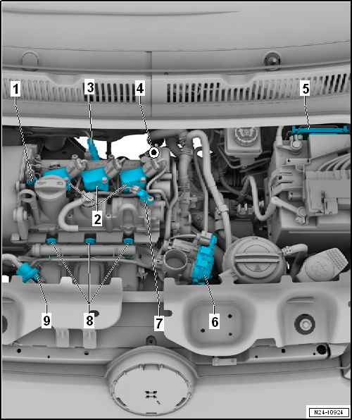
- Valve 1 for camshaft adjustment -N205-
- Ignition Coils with Output Stages
- Ignition coil 1 with output stage -N70-
- Ignition coil 2 with output stage -N127-
- Ignition coil 3 with output stage -N291-
- Removing and Installing "Ignition Coils with Output Stages"
- Lambda sensor 1 before catalytic converter -GX10-
- Removing and Installing "Lambda Sensor 1 before Catalytic Converter -GX10-"
- Lambda sensor 1 after catalytic converter -GX7-
- Removing and Installing "Lambda Sensor 1 after Catalytic Converter -GX7-"
- Engine control module -J623-
- Removing and Installing "Engine Control Module -J623-"
- Throttle valve control unit -J338-
- Removing and Installing "Throttle Valve Control Unit -J338-"
- clean
- Hall sender -G40-
- Removing and Installing "Hall Sensor -G40-"
- Fuel Injectors
- Fuel injector for cylinder 1 -N30-
- Fuel injector for cylinder 2 -N31-
- Fuel injector for cylinder 3 -N32-
- Removing and Installing "Fuel Injectors"
- Testing "Testing Fuel Injectors"
- Solenoid valve 1 for activated charcoal canister -N80-
Installation Location Overview Engine, Intake Side

- Oil pressure switch -F1-
- Remove and install
- Testing Oil Pressure and Oil Pressure Switch
- Intake manifold pressure sensor -G71- with intake air temperature sensor -G42-
- Removing and Installing "Intake Air Temperature Sensor -G42- / Intake Manifold Pressure Sensor -G71-"
- Engine speed sensor -G28-
- Removing and Installing "Engine Speed Sensor -G28-"
Installation Location Overview Engine, Exhaust Side

- Knock sensor 1 -G61-
- Removing and Installing "Knock Sensor 1 -G61-"
- Coolant temperature sender -G62-
- Remove and install
Assembly Overview - Fuel System
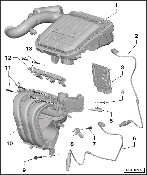
- Air filter
- Removing and Installing "Air Filter Housing"
- Lambda sensor 1 before catalytic converter -GX10-
- Grease only the thread with "G 052 112 A3"; "G 052 112 A3" must not get onto the slots of the probe body
- Removing and Installing "Lambda Sensor 1 before Catalytic Converter -GX10-"
- 50 N·m
- Engine control module -J623-
- Removing and Installing "Engine Control Module -J623-"
If engine control module -J623- is to be replaced, connect the → Vehicle diagnostic tester and perform "Guided Function, Replacing Engine Control Module".
Adapt engine control module -J623- to electronic immobilizer → Vehicle diagnostic tester "Guided Function"- Bolt
- for engine speed sensor -G28-
- 8 N·m
- Coolant temperature sender -G62-
- Remove and install
- If necessary, relieve pressure from cooling system before removal
- Lambda sensor 1 after catalytic converter -GX7-
- Grease only the thread with "G 052 112 A3"; "G 052 112 A3" must not get onto the slots of the probe body
- Removing and installing with "Removing and Installing Lambda Sensor 1 after Catalytic Converter -GX7-"
- 50 N·m
- Bolt
- for knock sensor
- 20 N·m
- Knock sensor
- Removing and Installing "Knock Sensor 1 -G61-"
- Bolt
- 20 N·m
- Intake manifold
- Removing and installing "Removing and installing intake manifold"
- Bolt
- 8 N·m
- 5 pieces
- Fuel rail with fuel injectors
- Fuel injector for cylinder 1 -N30-
- Fuel injector for cylinder 2 -N31-
- Fuel injector for cylinder 3 -N32-
- Removing and Installing "Assembly Overview - Fuel Rail with Fuel Injectors"
- Bolt
- 7 N·m
Relieving Fuel High Pressure
Risk of injury from high fuel pressure. The fuel injection system is divided into a high-pressure section (maximum approx. 120 bar) and a low-pressure section (approx. 7 bar). Before opening the high-pressure section, e.g. when removing the high-pressure pump, fuel rail, fuel injectors, fuel lines or fuel pressure sensor -G247-, fuel pressure in the high-pressure section must be reduced to a residual pressure of approx. 7 bar. The procedure for this is described below.
Required Special Tools, Test and Measuring Equipment and Auxiliary Items
- Vehicle diagnostic tester
Relieving Fuel High Pressure:
- Connect vehicle diagnostic tester and perform the function "Relieving Fuel High Pressure" under "Guided Functions".
- Fuel pressure drops to a specified value.
- Switch the ignition off.
The fuel rail is still filled with fuel, but it is no longer under high pressure.
Risk of injury. Avoid skin contact with fuel. Wear safety goggles and protective clothing when opening the fuel system. To catch escaping fuel, place a clean rag around the connection point before opening the high-pressure section.
- After relieving fuel high pressure, the high-pressure system must be opened "immediately". Place a clean rag around the connection point. Escaping fuel must be caught.

Note
- If the high-pressure system is not opened immediately, the pressure will build up again due to heat soak.
- The ignition must not be switched on now, otherwise the pressure will increase again.
Concluding Measures
- Clear fault memory and, in "Guided Functions" operating mode, generate the readiness code in the engine control module.