Intake manifold
Installation overview - Intake manifold
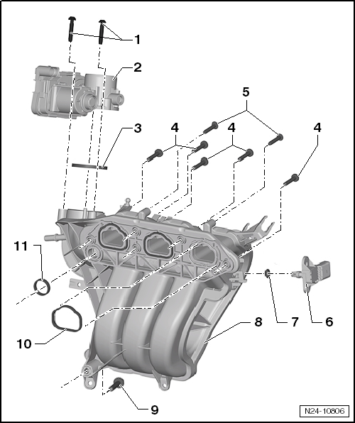
- Bolt
- 3 pcs.
- 7 N·m
- Throttle valve control unit -J338-
- clean
- 6-pin connector
- Contacts gold-plated
- Removing and Installing "Throttle Valve Control Unit -J338-"
- When replacing, adapt engine control module -J623- to throttle valve control unit -J338- → Vehicle diagnostic tester "Guided Function"
- Sealing ring
- Replace if damaged
- Bolt
- 5 pieces
- 8 N·m
- Bolt
- for the fuel rail
- 7 N·m
- Intake manifold pressure sensor -G71- with intake air temperature sensor -G42-
- Removing and Installing "Intake Air Temperature Sensor -G42- / Intake Manifold Pressure Sensor -G71-"
- Repair solution if locating lug is missing: "Removing and installing intake air temperature sensor -G42-/intake manifold pressure sensor -G71-"
- 4-pin connector
- Contacts gold-plated
- 3 N·m
- O-ring
- Replace if damaged
- Intake manifold
- Removing and installing "Removing and installing intake manifold"
- Bolt
- 20 N·m
- Sealing ring
- Replace if damaged
- Sealing ring
- Replace if damaged
Removing and installing intake manifold
Required Special Tools, Test and Measuring Equipment and Auxiliary Items
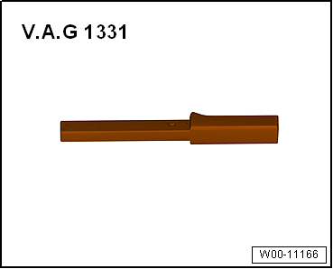
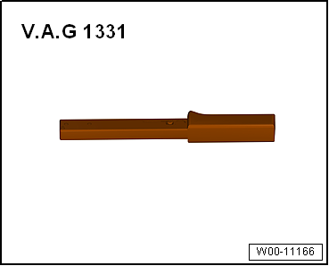
- Torque Wrench -V.A.G 1331-
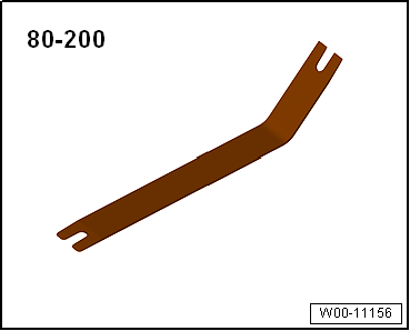
- Release lever -80 - 200-
Removing
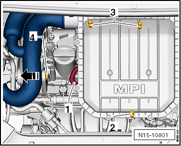
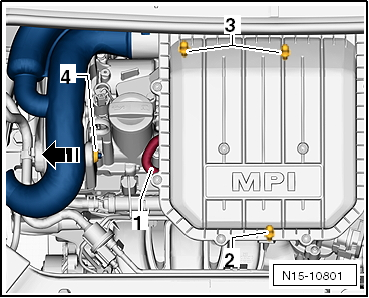
- Disconnect hose -1- from air filter housing.
- Pull air filter housing upward off the bolts at points -2- and -3-.
- Push the air filter housing with the intake connector out of mount -4- in the -arrow direction-.
- Remove the air filter housing from the engine compartment.
- Move lock carrier into service position → Body assembly work, exterior.
- Unlock and disconnect connector -2-.
- Disconnect hose -3- from throttle valve control unit -J338-.
- Disconnect line -4-.
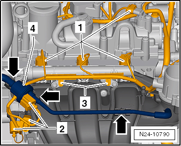
- Unlock and disconnect connectors -1- and -2-.
- Unclip wiring harness from brackets -3- on fuel rail and move it to the side.
- Unclip line -4- from brackets -arrows-.
- Remove line -4- together with solenoid valve 1 for charcoal canister -N80- and move it to the side.

Note
- The fuel line does not need to be opened.
- Do not remove injection valves from fuel rail.
- Remove fuel rail with injectors and set aside. See "Removing and installing injection valves".
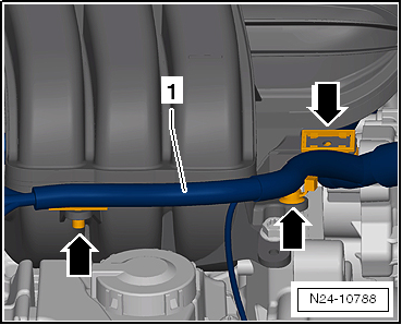
- Remove wiring harness -1- from brackets -arrows- on intake manifold.
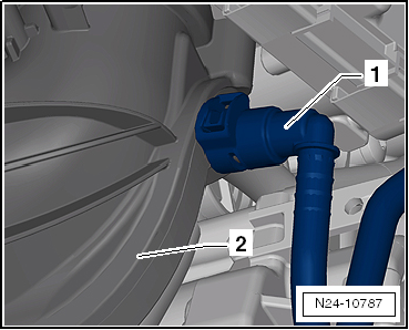
- Remove vacuum line -1- from intake manifold -2-.
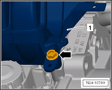
- Unscrew bolt -arrow- from bottom of intake manifold.
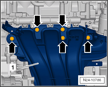
- Unscrew bolts -arrows-.
- Remove intake manifold -1-.
- If the intake manifold is to be replaced, remove throttle valve control unit -J338-. See "Removing and installing throttle valve control unit -J338-".
Installing
Installation is carried out in the reverse order. Observe the following:
- Make sure the seals are correctly seated.
Tightening torques
- "Assembly overview - Intake manifold"
Removing and installing throttle valve control unit -J338-
Required Special Tools, Test and Measuring Equipment and Auxiliary Items
- Torque Wrench -V.A.G 1331-
Removing
- Disconnect hose -1- from air filter housing.
- Pull air filter housing upward off the bolts at points -2- and -3-.
- Push the air filter housing with the intake connector out of mount -4- in the -arrow direction-.
- Remove the air filter housing from the engine compartment.
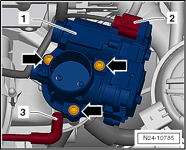
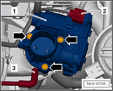
- Unlock and disconnect connector -2- on throttle valve control unit -J338--1-.
- Disconnect hose -3-.
- Unscrew bolts -arrows- and remove throttle valve control unit -J338-.
Installing
Installation is carried out in the reverse order. Observe the following:
- Check throttle valve control unit -J338- for cleanliness.
- Make sure the seal is seated correctly.
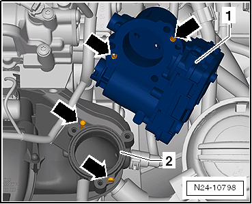
- Make sure guides -arrows- are correctly seated.
- Throttle valve control unit -J338--1- must be placed precisely on intake manifold -2-.
- When replacing, adapt throttle valve control unit -J338- to engine control module -J623- → Vehicle diagnostic tester "Guided Function".
Tightening torques
- "Assembly overview - Intake manifold"
Cleaning throttle valve control unit -GX3-

Note
- If a new engine control module -J623- is installed, the throttle valve control unit must be adapted.
- Dirt and coking in the end stop can lead to incorrect adaptation values.
- The throttle valve housing must not be scratched during cleaning.
Required Special Tools, Test and Measuring Equipment and Auxiliary Items
- Acetone, commercially available
- Brush
Work sequence
- Remove throttle valve control unit -GX3-.
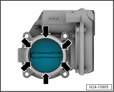
- Open throttle valve by hand and secure it in the open position with a plastic or wooden wedge -arrow-.
Risk of injury from acetone. Acetone is highly flammable and can cause eye and skin irritation. Wear safety goggles. Wear protective gloves.
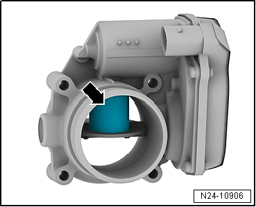
- Thoroughly clean throttle valve housing with commercially available acetone and a brush, especially in the area -arrows- of the closed throttle valve.
- Wipe throttle valve housing with a lint-free cloth.
- Allow acetone to evaporate completely.
- Install throttle valve control unit -GX3-.
- Erase adaptation values and adapt engine control module -J623- to throttle valve control unit -GX3-. Use a vehicle diagnostic tester.