Fuel Injectors
Assembly Overview - Fuel Rail with Fuel Injectors
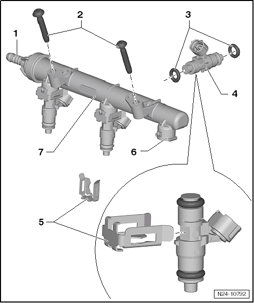
- Supply line
- black with white marking
- Secure with spring band clamps
- Make sure it is seated securely
- from fuel filter
- Bolt
- 7 N·m
- O-ring
- Replace
- Before installation, lightly wet with clean engine oil
- Fuel injector
- Fuel injector for cylinder 1 -N30-
- Fuel injector for cylinder 2 -N31-
- Fuel injector for cylinder 3 -N32-
- Removing and Installing "Fuel Injectors"
- Check tightness and injection quantity of fuel injectors "Testing Fuel Injectors"
- Retaining clip
- Make sure the injection valves and fuel rail are seated correctly
- Seating of the injection valves
- Make sure the retaining clip on the fuel rail is seated correctly
- Fuel rail with fuel injectors
- Check tightness and injection quantity of fuel injectors "Testing Fuel Injectors"
Removing and installing injection valves
Required Special Tools, Test and Measuring Equipment and Auxiliary Items
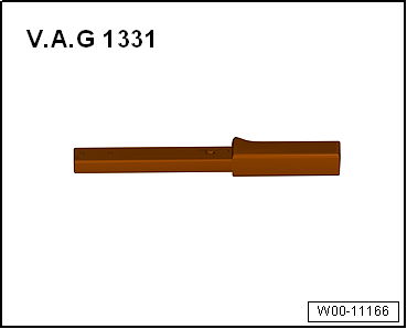
- Torque Wrench -V.A.G 1331-
Removing
- Disconnect hose -1- from air filter housing.
- Pull air filter housing upward off the bolts at points -2- and -3-.
- Push the air filter housing with the intake connector out of mount -4- in the -arrow direction-.
- Remove the air filter housing from the engine compartment.

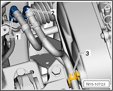
- Unlock and disconnect connectors -1- and -2-.
- Unclip the retaining clips -3- for the wiring harness from the fuel rail.

- Unlock and disconnect fuel supply line -1- → Fuel supply - petrol engines.
- Open cable routing -3- and remove hoses.
- Seal the line so that no dirt can enter the fuel system.
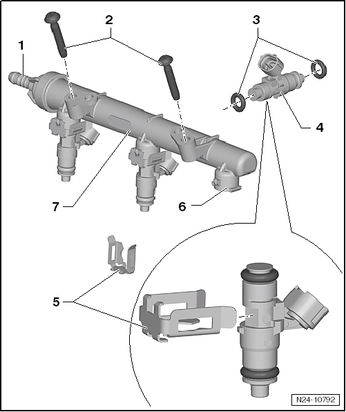
- Unscrew bolts -2- from the intake manifold.
- Pull the fuel rail -7- out of the intake manifold together with the injection valves -4-.
- Carefully remove retaining clip -5- of the injection valve to be removed.
- Pull the injection valve off the fuel rail.
Installing
Installation is carried out in the reverse order. Observe the following:
- Replace the sealing rings.
- Lightly coat the sealing rings with clean engine oil before installation.
- Make sure the sealing rings are seated correctly.
- Observe the installed position of the retaining clips.
- Make sure the injection valves -4- are seated correctly on connection -6-.

Checking injection valves
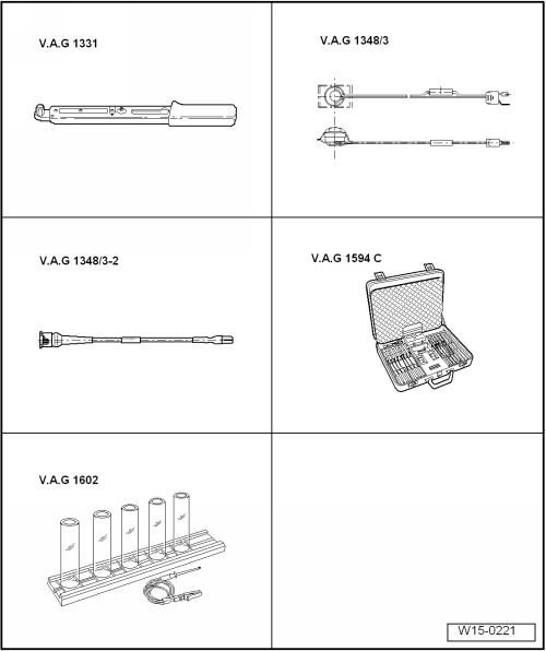
Required Special Tools, Test and Measuring Equipment and Auxiliary Items
- Torque Wrench -V.A.G 1331-
- Remote control to V.A.G 1348 -V.A.G 1348/3A-
- Adapter lead -V.A.G 1348/3-2-
- Measuring adapter set -V.A.G 1594 C-
- Injection quantity tester -V.A.G 1602-
- Digital potentiometer -V.A.G 1630-
Checking injection quantity and spray pattern of the injection valves
Test conditions
- Fuel pressure OK → Fuel supply - petrol engines.
Test procedure
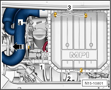
- Disconnect hose -1- from air filter housing.
- Pull air filter housing upward off the bolts at points -2- and -3-.
- Push the air filter housing with the intake connector out of mount -4- in the -arrow direction-.
- Remove the air filter housing from the engine compartment.
- Remove the fuel rail together with the injection valves, see "Removing and installing injection valves".

Note
Leave the fuel rail loosely inserted in the intake manifold so that no dirt enters the intake manifold while the test equipment is connected.
- The fuel hoses remain connected.
- The injection valves are not disconnected from the fuel rail.
- All electrical connectors of the injection valves must be disconnected.
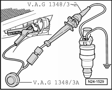
- Connect one contact of the injection valve to be tested to the remote control -V.A.G 1348/3A- using adapter lead -V.A.G 1348/3-2-.
- Connect the other contact of the injection valve to be tested to engine ground using measuring adapter set -V.A.G 1594C-.
- Assemble the ground lead using measuring leads -V.A.G 1594/2-, measuring leads -V.A.G 1594/19- and a tap clamp -V.A.G 1594/14-.
- Connect the tap clamp to the battery (+) in the engine compartment.
- For a comparative quantity measurement, take 3 measuring glasses from the injection quantity tester -V.A.G 1602-.
- Use one measuring glass for each injection valve being tested.
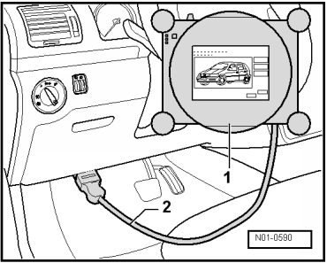
- Connect the → Vehicle diagnostic tester as follows:
- Plug the connector of the diagnostic lead -2- into the diagnostic connector in the driver's footwell.

Note
- The relay for the electric fuel pump is only activated for 30 seconds during the actuator test.
- As soon as the actuator test starts, the button on the remote control -V.A.G 1348/3A- must be pressed at the same time.
- The remote control -V.A.G 1348/3A- must be operated until no more fuel drips from the valve.
- Switch the ignition on.
- Operate the following buttons on the display one after another.
- Diagnostic mode
- 01 - Engine electronics
- 005 - Actuator test
- Fuel pump relay
- Start

Note
- An ignition cycle must be performed between the tests of the individual injection valves.
- If no ignition cycle is performed, the actuator test may not be possible more than once.
- Repeat the test on the other injection valves.
- After all injection valves have been activated, place the measuring glasses on a level surface and compare the injection quantities.

Note
- When the actuator test ends, fuel is still in the lines and in the valve and continues to drip after the actuator test.
- This residual quantity is approx. 6 ml. The residual quantity must be subtracted from the total quantity by calculation.
- A calculation example is shown in the table below!
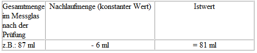
Nominal value: 76 ... 82 ml per valve
If the measured value of one or more injection valves is below or above the specified nominal value:
- Replace the defective injection valve, see "Assembly overview - fuel system".
Check for leaks
Test conditions
- Fuel pressure OK
- Engine and fuel temperature approx. 20 ºC.
- Fuel rail is removed.
- The electrical connectors of all injection valves are disconnected.
- As a precaution, place a measuring glass -V.A.G 1602/1- under all injection valves.

Note
- Pressure is built up in the fuel system during the leak test.
- The valves are not activated.
- If fuel now escapes from the valves, they are defective.
- Connect the → Vehicle diagnostic tester as follows:
- Plug the connector of the diagnostic lead -2- into the diagnostic connector in the driver's footwell.
- Switch the ignition on.
- Operate the following buttons on the display one after another.
- Diagnostic mode
- 01 - Engine electronics
- 005 - Actuator test
- Fuel pump relay
- Start
- Switch the ignition off.
Nominal value: No more than 2 drops may escape during the actuator test.
If the fuel loss is greater:
- Replace the defective injection valve, see "Assembly overview - fuel system".
Installation of the injection valves is performed in the reverse order of removal, observing the following:
- Replace the O-rings on all injection valves and lightly coat them with clean engine oil.
Tightening torques:
- Position the fuel rail with the secured injection valves on the intake manifold and tighten evenly, see "Assembly overview - fuel system".
