Fuel pump unit/fuel level sender
Assembly overview - Fuel pump unit/fuel level sender
Assembly overview - Fuel pump unit/fuel level sender, vehicles with union nut

Note
- Hose connections are secured with spring band clamps or clamps.
- Replace clamps with spring band clamps.
- Fuel hoses on the engine may only be secured with spring band clamps. The use of clamps or screw clamps is not permitted.
- Hose clamp pliers -VAS 6340- are recommended for installing spring band clamps.
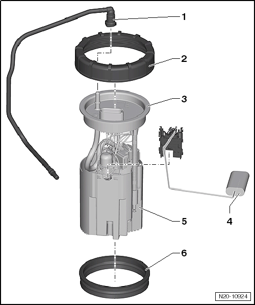
- Supply line
- black
- clipped onto side of fuel tank
- Make sure it is seated securely
- Union nut
- 80 N·m
- Loosen with wrench -3217-
- Flange
- for fuel pump unit
- Observe installed position of flange on fuel tank
- Fuel level sender -G-
- Remove and install
- Fuel Pump Unit
- Remove and install
- with fuel pump for pre-supply -G6-
- Fuel pump for pre-supply -G6-
- Sealing ring
- Replace
- Insert dry into opening of fuel tank for installation
- Wet with fuel only for installing flange
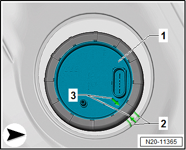
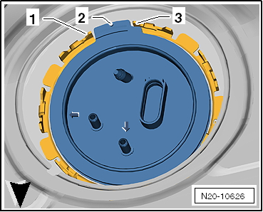
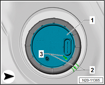
Installed position of fuel pump unit flange
- There is an arrow between the marks -2- on the fuel tank.
- There is an arrow on locking flange -1-.
- The two arrows -3- must face each other during installation.
Assembly overview - Fuel pump unit/fuel level sender, vehicles with locking ring
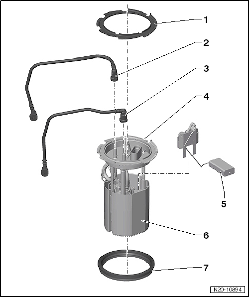
- Locking ring
- 110 N·m
- Supply line
- black
- clipped onto side of fuel tank
- Make sure it is seated securely
- Return line
- blue
- clipped onto side of fuel tank
- Make sure it is seated securely
- Flange
- for fuel pump unit
- Observe installed position of flange on fuel tank
- Fuel level sender -G-
- Remove and install
- Fuel Pump Unit
- Remove and install
- with fuel pump for pre-supply -G6-
- Check Fuel Pump
- Sealing ring
- Replace
- Insert dry into opening of fuel tank for installation
- Wet with fuel only for installing flange
Installed position of locking flange
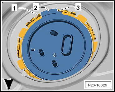
- Press locking flange down against spring force and bring the locking flange into installed position.
- Tab -2- on locking flange must lie between lugs -1- and -3- on fuel tank.
- The -arrow- points in direction of travel.
Removing and installing fuel pump unit/fuel level sender
Removing and installing fuel pump unit/fuel level sender, vehicles with union nut
Required Special Tools, Test and Measuring Equipment and Auxiliary Items
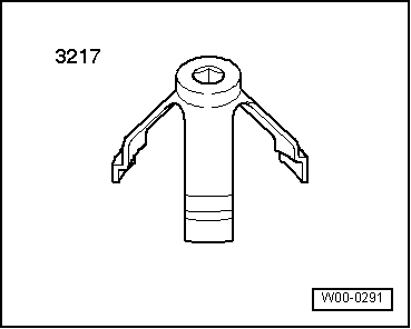
- Wrench -3217-
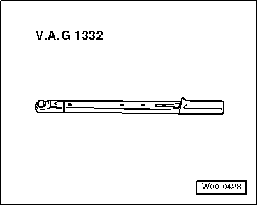
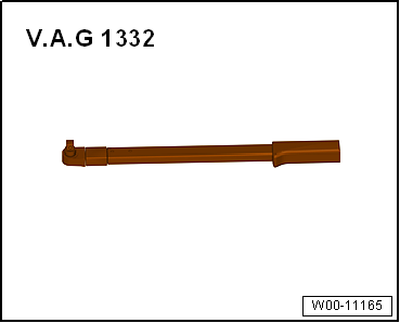
- Torque Wrench -V.A.G 1332-
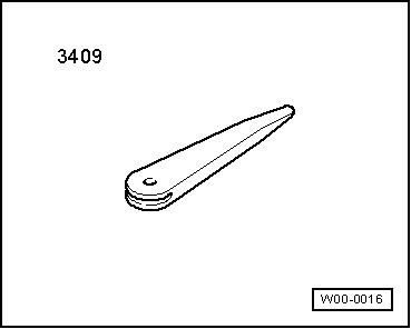
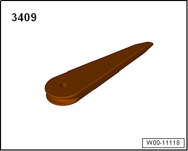
- Release Wedge -3409-
Removing
- Empty fuel tank with fuel extraction unit -VAS 5190-.
- Disconnect the negative battery cable → Electrical System.
- Remove rear seat bench → Body assembly work interior.
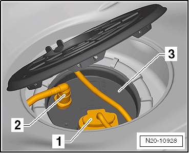
- Unclip cover -1- from the retaining clips using demolding wedge -3409- -arrows-.
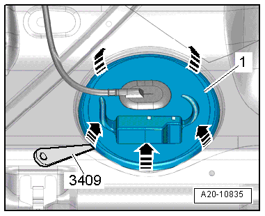
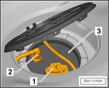
- Unlock connector -1- and disconnect it.

WARNING!
The fuel line is under pressure!
Risk of eye and skin injury from fuel.
Wear safety goggles and protective clothing to avoid injury and skin contact. Before loosening hose connections, place a cleaning rag around the connection point. Then relieve pressure by carefully opening the connection point.
- Unlock and disconnect fuel lines -2- from fuel pump unit -3-. Disconnect plug-in connectors.
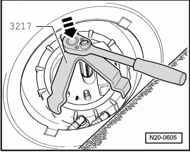
- Loosen union nut with wrench -3217-.
- Pull locking flange out of fuel tank opening.
- Remove sealing ring from fuel tank opening.
- Place rag underneath to catch fuel.
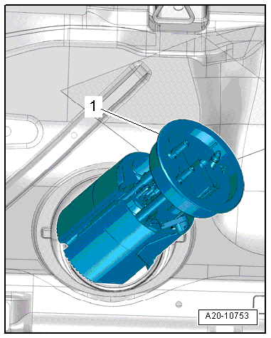
- Carefully pull fuel pump unit -1- with fuel level sender out through the fuel tank installation opening.
- When removing the fuel pump unit, make sure the float arm of fuel level sender -G- is not bent.
- Check fuel tank for contamination.

Note
- If the pump unit is to be replaced, the old pump unit must be emptied before disposal.
- Observe disposal regulations.
Installing
Installation is carried out in the reverse order. Observe the following:
- Replace sealing ring.
- Insert sealing ring of fuel pump unit dry into fuel tank opening.
- Wet inside of sealing ring with fuel.
- When inserting the fuel pump unit, make sure the fuel level sender is not bent.
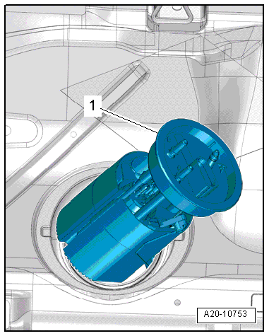
- Press locking flange -1- down against spring force.
- Bring the locking flange into installed position.
- There is an arrow between the marks -2- on the fuel tank.
- There is an arrow on locking flange -1-.
- The two arrows -3- must face each other during installation.
- Tighten union nut.
- Attach connector -1-.
- Attach fuel line -2-.
- Check that the plug-in connector and connector are secure by pulling against them!
Tightening torque
- "Assembly Overview - Fuel Pump/Fuel Level Sender"
Removing and installing fuel pump/fuel level sender, vehicles with locking ring
Required Special Tools, Test and Measuring Equipment and Auxiliary Items
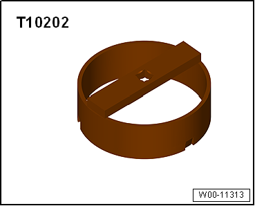
- Wrench -T10202-
- Release Wedge -3409-
- Torque Wrench -V.A.G 1332-
Removing
- Empty fuel tank with fuel extraction unit -VAS 5190-.
- Disconnect the negative battery cable → Electrical System.
- Remove rear seat bench → Body assembly work interior.
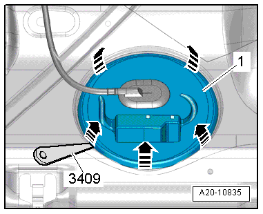
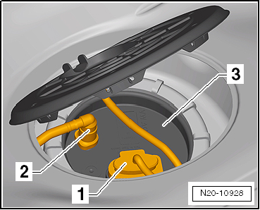
- Unclip cover -1- from the retaining clips using demolding wedge -3409- -arrows-.
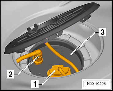
- Unlock connector -1- and disconnect it.

WARNING!
The fuel line is under pressure!
Risk of eye and skin injury from fuel.
Wear safety goggles and protective clothing to avoid injury and skin contact. Before loosening hose connections, place a cleaning rag around the connection point. Then relieve pressure by carefully opening the connection point.
- Unlock and disconnect fuel lines -2- from fuel pump unit -3-. Disconnect plug-in connectors.
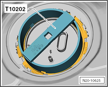
- Open the locking ring with key -T10202- and lift the flange slightly.
- Pull locking flange out of fuel tank opening.
- Remove sealing ring from fuel tank opening.
- Place rag underneath to catch fuel.
- Carefully pull fuel pump unit -1- with fuel level sender out through the fuel tank installation opening.
- When removing the fuel pump unit, make sure the float arm of fuel level sender -G- is not bent.
- Check fuel tank for contamination.

Note
- If the pump unit is to be replaced, the old pump unit must be emptied before disposal.
- Observe disposal regulations.
Installing
Installation is carried out in the reverse order. Observe the following:
- Replace sealing ring.
- Insert sealing ring of fuel pump unit dry into fuel tank opening.
- Wet inside of sealing ring with fuel.
- When inserting the fuel pump unit, make sure the fuel level sender is not bent.
- Press locking flange down against spring force and bring the locking flange into installed position.
- Tab -2- on locking flange must lie between lugs -1- and -3- on fuel tank.
- The -arrow- points in direction of travel.
- Attach connector -1-.
- Attach fuel line -2-.
- Check that the plug-in connector and connector are secure by pulling against them!
Tightening torque
- "Assembly Overview - Fuel Pump/Fuel Level Sender"
Removing and installing fuel level sender
Removing
- Observe safety precautions.
- Observe cleanliness rules.
- Remove fuel pump.
- Pull fuel level sender -G- slightly to the side and up at the same time.
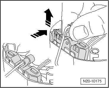
- Release the latching lugs -arrows- inward.
- Pull fuel level sender -G- upward out of the fuel pump.
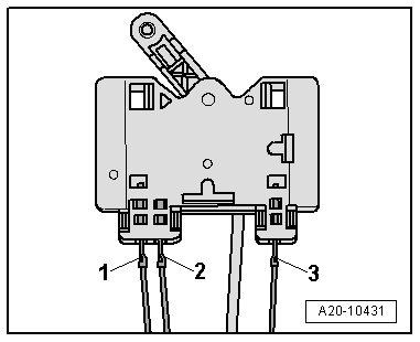
- Note the color assignment of the wires for reinstallation.
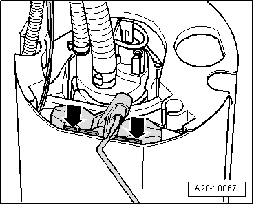
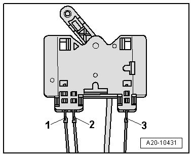
- Unlock and disconnect connectors -1- to -3-.
- Bend back the latching hooks of the connectors.
Installing:
- Connect connectors -1- to -3-.
- Observe color assignment.
- Check that the connectors are firmly seated by pulling against them!
- Insert fuel level sender -G- into the guide on the fuel pump and press down until it engages.
- Install fuel pump.