Fuel Tank
Assembly Overview - Fuel Tank
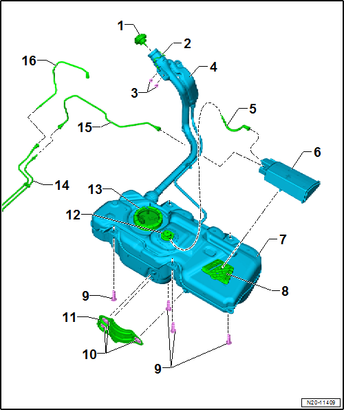
- Filler Cap
- Replace if damaged
- Ground Cable
- Bolt
- 8 N·m +90º
- 2 pieces
- Replace
- Filler Neck
- Breather Line
- clipped onto fuel tank
- Make sure it is seated securely
- Connection
- Activated Charcoal Canister
- Assembly Overview
- Check Venting
- Remove and install
- Fuel Tank
- When removing, support with Engine and Transmission Hoist -V.A.G 1383 A-
- Remove and install
- Bracket for Activated Charcoal Canister
- Bolt
- 20 N·m +90º
- 4 pieces
- Replace
- Clamp Washer
- Heat Shield
- Gravity Valve
- Fuel Pump Unit
- Assembly Overview
- Remove and install
- Check Fuel Pump
- with Fuel Level Sender -G-
- Remove and install Fuel Level Sender -G-
- Clean filter screen if dirty
- Breather Line
- Make sure it is seated securely
- to connection
- Breather Line
- clipped onto fuel tank
- Make sure it is seated securely
- Connection
- Fuel Line
- to engine
Remove and install fuel tank
Required Special Tools, Test and Measuring Equipment and Auxiliary Items
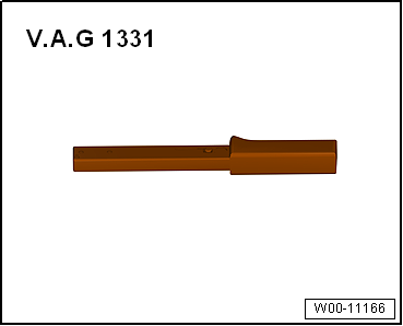
- Torque Wrench -V.A.G 1331-
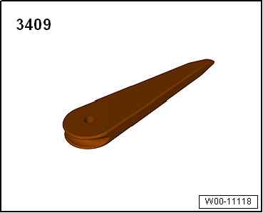
- Release Wedge -3409-
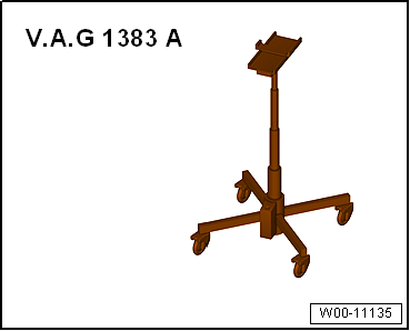
- Engine and Transmission Hoist -V.A.G 1383 A-
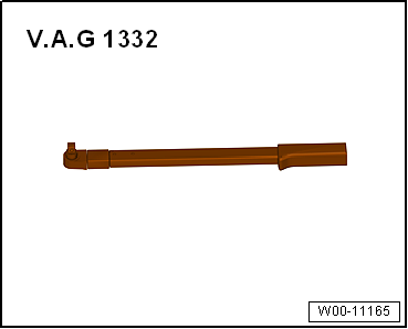
- Torque Wrench -V.A.G 1332-
Removing
- Disconnect the negative battery cable → Electrical System.
- Open the fuel filler flap.
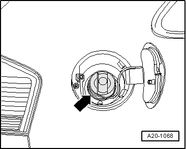
- Remove the filler cap -arrow- from the fuel filler neck.
- Clean the area around the fuel filler neck.
- Drain the fuel tank completely.
- Remove the fuel filler flap unit → Body Assembly Work, Exterior.
- Remove the seat bench → Body Assembly Work, Interior.

- Unclip cover -1- from the retaining clips using demolding wedge -3409- -arrows-.

- Unlock connector -1- and disconnect it.
- Remove rear right wheel → Wheels, Tires, Wheel Alignment.

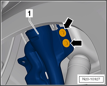
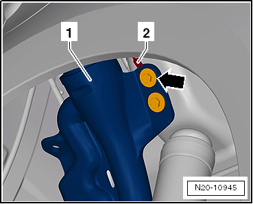
- Unscrew bolts -arrows- of filler neck -1- from the body.

Note
A second mechanic is required to remove the rear section of the exhaust system.
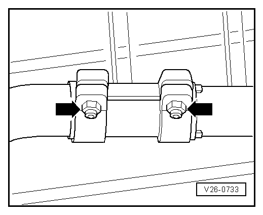
Vehicles with a clamping sleeve on the exhaust system
- If fitted, loosen clamping sleeve -arrows-.
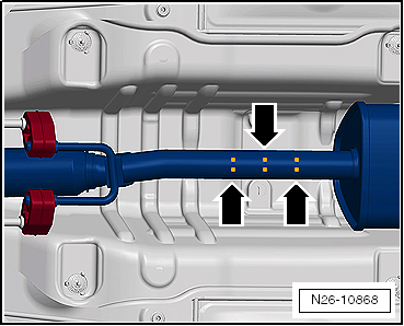
Vehicles without a clamping sleeve on the exhaust system
On vehicles without a clamping sleeve, separate the exhaust system.
Continuation for all vehicles
- Remove crossmember -1- on the underbody for the exhaust system -2-.
- Unscrew nuts -arrows-.
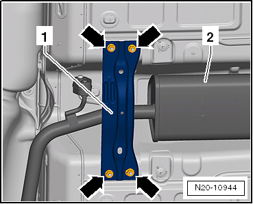
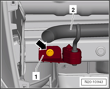
- Remove rear bracket -1- for the exhaust system -2-.
- Unscrew bolt -arrow-.
- Remove rear silencer.

WARNING!
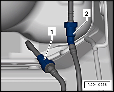
The fuel supply line is under pressure! Wear safety goggles and protective gloves to avoid injury and skin contact. Before loosening hose connections, place a rag around the connection point. Then relieve pressure by carefully pulling off the hose.
- Open fuel lines. Disconnect quick-connect couplings.
- Lower rear axle → Suspension, Axles, Steering.
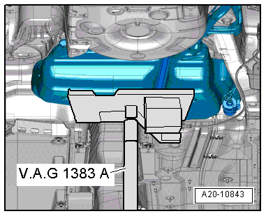
- Position engine and transmission jack -V.A.G 1383 A- under the fuel tank to support it.
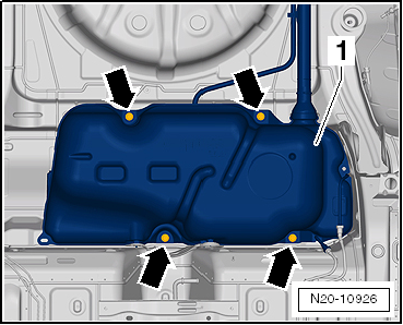
- Unscrew bolts -arrows- from fuel tank -1-.

Note
A second mechanic is required to remove the fuel tank.
- Lower the fuel tank and guide it out of the body.
If the fuel tank is being replaced, remove the activated charcoal canister.
Installing
Installation is carried out in the reverse order. Observe the following:
- Make sure the fuel tank filler neck is correctly inserted into the opening in the body.
- Position the fuel tank on the underbody using the engine and transmission jack -V.A.G 1383 A-.
- Make sure the activated charcoal canister is correctly seated.
- Route vent and fuel lines without kinks.
- Make sure line connections are securely seated.
- After installing the fuel tank, check that the supply and vent lines are still clipped to the fuel tank.
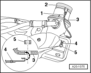
- Route the ground connection as shown in the illustration.
- Hook contact tongue -4- of the ground connection into the mounting hole on fuel tank -3-, then press in spacer bushing -5-.
- Make sure connector -1- of the ground connection is securely seated on sheet metal ring -2- of the fuel filler neck.
- Bolt contact tongue -2- of the ground connection to fuel filler neck -1- using flange bolt -arrow-.
- After installation, check the electrical connection.
- Check the connection between the sheet metal ring on the fuel filler neck and a bare metal point on the body.
- Use an ohmmeter for this. Nominal value is approx. 0 ohms.
- Fill at least 5 litres of fuel into the fuel tank.

WARNING!
Risk of explosion of the fuel tank! After installing a new or completely drained fuel tank, a minimum quantity of 5 litres of fuel must be added immediately. The fuel pump must not run in a completely empty fuel tank.
Tightening torque
- "Assembly Overview - Fuel Tank"
- → Body Assembly Work, Interior
- → Body Assembly Work, Exterior
Draining the fuel tank
Draining the fuel tank with an intact fuel pump

Caution!
Attach the ground lead of the fuel extraction unit to a bare metal point on the body.
To extract E85 fuel, only use fuel extraction unit -VAS 5190 A-!
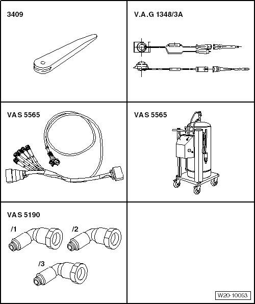
Required Special Tools, Test and Measuring Equipment and Auxiliary Items
- Release Wedge -3409-
- Remote control -V.A.G 1348/3A-
- Adapter for measuring technology/DSO (5-pin) -VAS 5565-
- Fuel extraction unit -VAS 5190-
- Fuel extraction unit -VAS 5190 A- (not illustrated) for E85 fuel.
- Adapter for fuel extraction -VAS 5190-

Note
If the fuel extraction unit -VAS 5190- is still fitted with the extraction hose with fixed tip, this must be replaced with the version with screw-on tip.
- Observe safety precautions.
- Observe cleanliness rules.
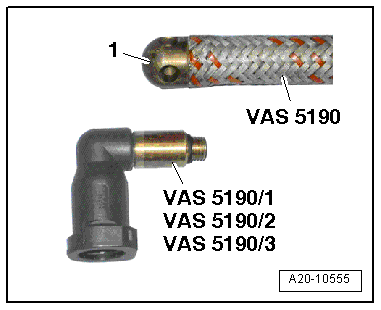
- Unscrew tip -1- from the extraction hose of fuel extraction unit -VAS 5190-.
- Screw adapter for fuel extraction -VAS 5190 /2- from the fuel extraction adapter set -VAS 5190 /10- onto the extraction hose.

WARNING!
- The fuel supply line is under pressure! Wear safety goggles and protective clothing to avoid injury and skin contact. Before loosening hose connections, place a rag around the connection point. Then relieve pressure by carefully pulling off the hose.
- Connect the ground lead of fuel extraction unit -VAS 5190- to vehicle ground.
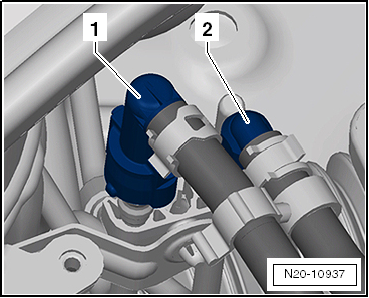
- Pull off supply line -1- (black) and catch escaping fuel with a rag. Disconnect quick-connect couplings.
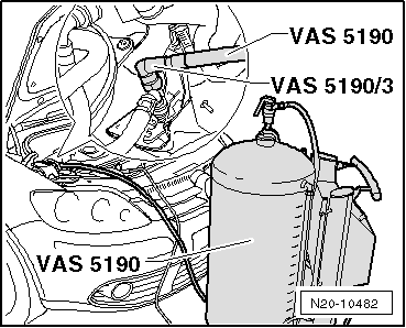
- Connect fuel extraction unit -VAS 5190- with adapter for fuel extraction -VAS 5190 /3- to the fuel supply line.
- Remove the seat bench → Body Assembly Work, Interior.
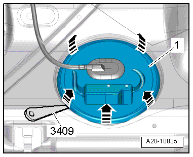
- Unclip cover -1- from the retaining clips using demolding wedge -3409- -arrows-.
- Unlock connector -1- and disconnect it.

- Plug adapter for measuring technology/DSO (5-pin) -VAS 5565- into the connector and the fuel pump unit.
- Connect remote control -V.A.G 1348/3A- to adapter for measuring technology/DSO (5-pin) -VAS 5565- and to battery positive (+).

Note
This step is only used to run the fuel pump with the engine off.
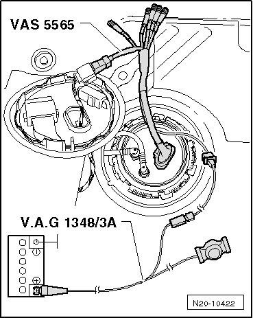
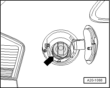
- Open the fuel filler flap.
- Remove the filler cap -arrow- from the fuel filler neck.
- Operate remote control -V.A.G 1348/3A- and shut-off valve on fuel extraction unit -VAS 5190- until the fuel tank is empty.

Caution!
The fuel pump must not run dry.
Draining the fuel tank when more than 3/4 full

Caution!
Attach the ground lead of the fuel extraction unit to a bare metal point on the body.
To extract E85 fuel, only use fuel extraction unit -VAS 5190 A-!
Required Special Tools, Test and Measuring Equipment and Auxiliary Items
- Fuel extraction unit -VAS 5190-
- Fuel extraction unit -VAS 5190 A- (not illustrated) for E85 fuel.
- Observe safety precautions.
- Observe cleanliness rules.
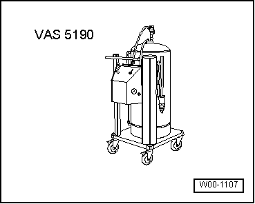
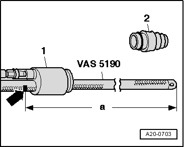
- Pull conical piece -2- off shaft piece -1- of fuel extraction unit -VAS 5190-.
- Mark the extraction hose with arrow -a- at a distance of 1340 mm from the end of the hose, using insulating tape.
- Open the fuel filler flap.
- Remove the filler cap -arrow- from the fuel filler neck.
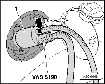
- Screw shank piece -1- of fuel extraction unit -VAS 5190- onto the fuel tank filler neck.
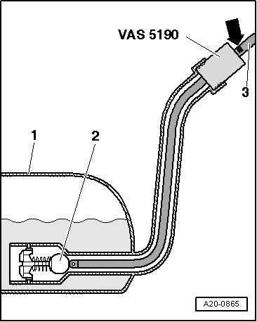
- Push the extraction hose into the fuel tank until the mark -arrow- made earlier lines up with the shank piece.

Note
At the lower end of the filler neck there is a ball valve -2- in fuel tank -1-, which must not be damaged by extraction hose -3-. Therefore, only insert the hose up to the mark -arrow- made earlier.
- Empty the fuel tank through the filler neck as far as possible.
- Carefully pull out the extraction hose.

Note
- If no more fuel can be extracted, the fuel tank is only emptied far enough that the sender flange can be opened safely.
- To remove the fuel tank, it must be completely emptied.
Draining fuel tank when less than 3/4 full

Caution!
Attach the ground lead of the fuel extraction unit to a bare metal point on the body.
To extract E85 fuel, only use fuel extraction unit -VAS 5190 A-!
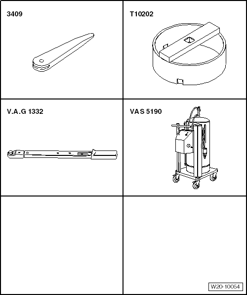
Required Special Tools, Test and Measuring Equipment and Auxiliary Items
- Release Wedge -3409-
- Wrench -T10202-
- Torque Wrench -V.A.G 1332-
- Fuel extraction unit -VAS 5190-
- Fuel extraction unit -VAS 5190 A- (not illustrated) for E85 fuel.

Note
- Plug-in connectors must audibly lock into place when engaged.
- When installing plug-in connectors, observe the color coding!
- Check that the plug-in connector is secure by pulling against it!
- Disconnect plug-in connectors.
- Observe safety precautions.
- Observe cleanliness rules.
- Remove the seat bench → Body Assembly Work, Interior.
- Unclip cover -1- from the retaining clips using demolding wedge -3409- -arrows-.

- Unlock connector -1- and disconnect it.

WARNING!
The fuel supply line is under pressure! Wear safety goggles and protective clothing to avoid injury and skin contact. Before loosening hose connections, place a rag around the connection point. Then relieve pressure by carefully pulling off the hose.
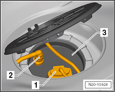
- Unlock and disconnect fuel lines -2- from fuel pump unit -3-. Disconnect plug-in connectors.
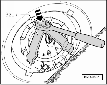
- Loosen union nut with wrench -3217-.
- Carefully lift the fuel pump unit flange.
- Insert suction hose of fuel extraction unit -VAS 5190- as deep as possible into the fuel tank.
- Extract fuel.
If the fuel tank is only to be drained, reinstall the fuel pump unit.
Tightening torque
