Fuel pump
Check Fuel Pump
Check function and power supply
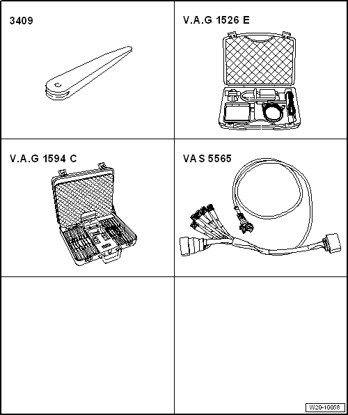
Required Special Tools, Test and Measuring Equipment and Auxiliary Items
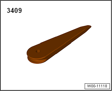
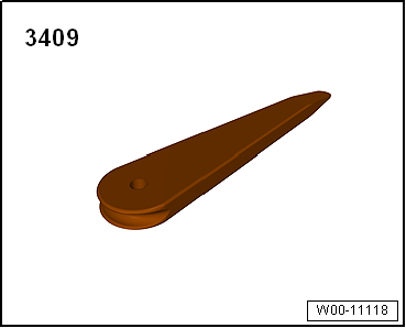
- Release Wedge -3409-
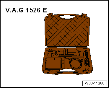
- Multimeter, e.g. hand-held multimeter -V.A.G 1526E-
- Measuring adapter set -V.A.G 1594C-
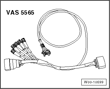
- Adapter for measuring technology/DSO (5-pin) -VAS 5565-
- Vehicle diagnostic tester
Test conditions:
- Battery voltage at least 11.5 V, charge battery if necessary → Electrical system.
- Fuse for fuel pump for pre-supply -G6- OK → Wiring diagrams, fault finding and component locations.
Test procedure:

Note
The function of the fuel pump is checked using output diagnostic test mode.
- Observe safety precautions.
- Observe cleanliness rules.
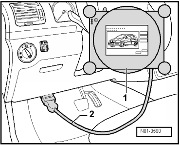
- Connect the vehicle diagnostic tester -1- as follows:
- Plug the connector of the diagnostic lead -2- into the diagnostic connector in the driver's footwell.
- Switch the ignition on.
- On the display, press the buttons for vehicle self-diagnosis, engine electronics and actuator test in sequence.
- On the display, press the right arrow button until the actuator test for the fuel pump electronics is reached.
The fuel pump must now start running.

Note
- The fuel pump runs very quietly.
- If the actuator test is to be carried out several times in succession, it may be necessary to start the engine briefly before repeating the actuator test.
- Switch the ignition off.
Fuel pump does not start:
- Remove the seat bench → Body Assembly Work, Interior.
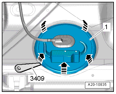
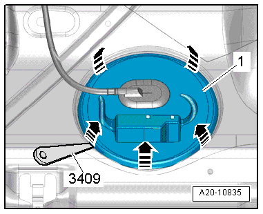
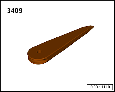
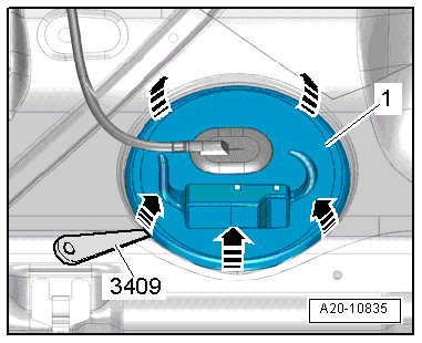
- Unclip cover -1- from the retaining clips using demolding wedge -3409- -arrows-.
- Check that connector -1- is seated firmly by pulling on the connector without pressing the locking tab. If the connector was not plugged in correctly, repeat the fuel pump function check.
- Unlock connector -1- and disconnect it.
- Check the contacts on the connector and on the fuel delivery unit -3- for damage.

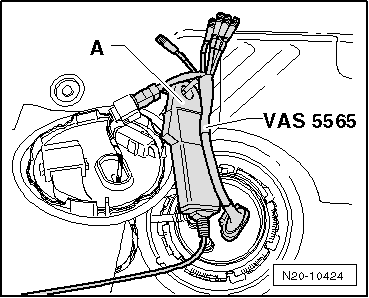
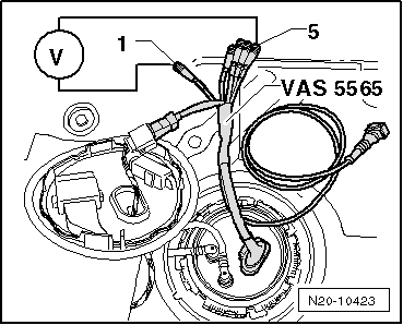
- Connect the measurement/DSO adapter (5-pin) -VAS 5565- to the connector and to the fuel delivery unit.
- Connect the hand-held multimeter -V.A.G 1526D- to wires -1- and -5- of the measurement/DSO adapter (5-pin) -VAS 5565-.
- Initiate the actuator test again and measure the voltage at the fuel pump.
- Nominal value: approx. battery voltage.
Power supply not OK:
- Locate and repair the open circuit using the wiring diagram → Wiring Diagrams, Electrical Troubleshooting and Component Locations.
Power supply OK:

WARNING!
The fuel line is under pressure!
Risk of eye and skin injury from fuel.
Wear safety goggles and protective clothing to avoid injury and skin contact. Before loosening hose connections, place a cleaning rag around the connection point. Then relieve pressure by carefully opening the connection point.

- Disconnect fuel line -2- from the fuel delivery unit -3-. Separate the quick-connect couplings.
- Unlock connector -1- and disconnect it.

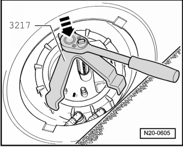
- Open the locking ring with the union nut wrench -3217-.
- Check whether the electrical wires between the flange and the fuel pump are connected.
- Check the contacts for damage.
If no open circuit is found:
- Fuel pump faulty, replace the fuel delivery unit.
Check fuel pressure
Required Special Tools, Test and Measuring Equipment and Auxiliary Items
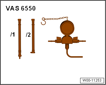
- Pressure gauge -VAS 6550-
- Release Wedge -3409-
- Vehicle diagnostic tester
- Observe safety precautions.
- Observe cleanliness rules.
- Battery charger is connected.
- Battery voltage at least 11.5 V, charge battery if necessary → Electrical system.
- Fuel level in the fuel tank is above reserve.
- Power supply OK.

WARNING!
The fuel line is under pressure!
Risk of eye and skin injury from fuel.
Wear safety goggles and protective clothing to avoid injury and skin contact. Before loosening hose connections, place a cleaning rag around the connection point. Then relieve pressure by carefully opening the connection point.
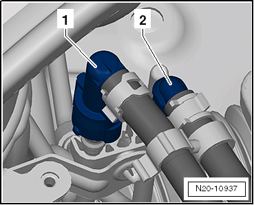
- Pull off supply line -1- (black) and catch escaping fuel with a rag. Disconnect quick-connect couplings.
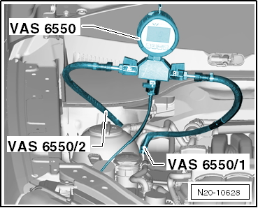
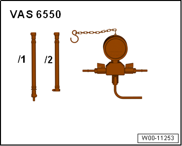
- Connect the pressure gauge -VAS 6550- with adapter -VAS 6550/1- and -VAS 6550/2- to the fuel supply line.
- Connect hose line -VAS 6550/1- to the fuel supply line to the engine and to connection -B-.
- Connect hose line -VAS 6550/2- to connection -A- of the pressure gauge -VAS 6550-.
- Connect the fuel line to the fuel tank to the pressure gauge -VAS 6550- using hose line -VAS 6550/2-.
- Check that the quick connectors are firmly seated by pulling against them!
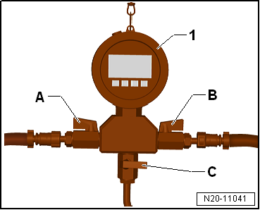
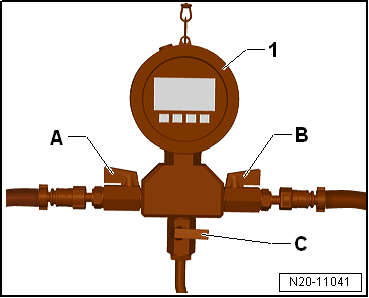
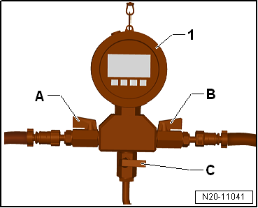
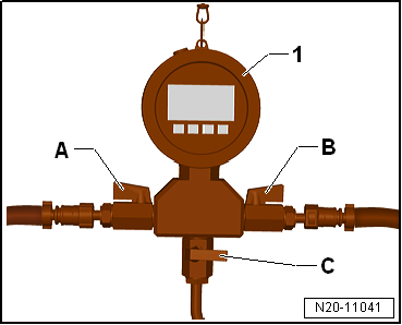
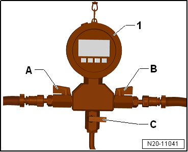
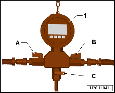
- Make sure that drain valve -C- on pressure gauge -VAS 6550--1- is closed.
- Shut-off valves -A- and -B- must be open on pressure gauge -VAS 6550--1-.
- Connect the vehicle diagnostic tester.
- On the display, press the buttons in sequence.
- Vehicle self-diagnosis
- Engine electronics
- Actuator test
- Electric fuel pump
- Button

Note
The fuel pump is now activated so that fuel pressure builds up.
- Read the fuel pressure on the pressure gauge.
- Nominal value: 3.0 ... 3.3 bar.
If the fuel pressure is OK, check the holding pressure.
If the nominal value is exceeded:
- Replace the fuel delivery unit.
If the nominal value is not reached:
- Check the fuel line for possible restrictions (kinks) or blockages.
- Check the fuel line for leaks and damage.
If no fault is found:
Check the fuel pressure at the underbody coupling point as follows:

WARNING!
The fuel line is under pressure!
Risk of eye and skin injury from fuel.
Wear safety goggles and protective clothing to avoid injury and skin contact. Before loosening hose connections, place a cleaning rag around the connection point. Then relieve pressure by carefully opening the connection point.
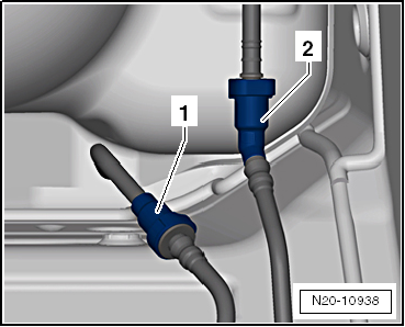
- Disconnect fuel supply line -2-. Separate the quick-connect couplings.
- Catch the escaping fuel with a shop rag.
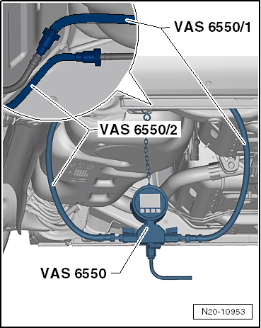
- Connect the pressure gauge -VAS 6550- with adapter -VAS 6550/1- and -VAS 6550/2- to the quick-connect couplings of the fuel supply line.
- Connect adapter -VAS 6550/1- to the fuel line to the engine compartment and to shut-off valve -B-.
- Connect hose line -VAS 6550/2- to the fuel line to the fuel tank and to shut-off valve -A-.
- Check that the quick connectors are firmly seated by pulling against them!
- Make sure that drain valve -C- on pressure gauge -VAS 6550--1- is closed.
- Shut-off valves -A- and -B- must be open on pressure gauge -VAS 6550--1-.
- Repeat the actuator test so that fuel pressure builds up.
- Slowly close shut-off valve -B-. The pressure must rise to at least 3.0 ... 3.3 bar. Once 3.0 ... 3.3 bar is reached, reopen the shut-off valve immediately!
If the nominal value is reached:
- Fuel pump OK. Check the fuel line to the engine compartment for possible restrictions (kinks) or blockages.
- Check the fuel line for leaks and damage.
If the nominal value is not reached:
Check the fuel pressure at the fuel delivery unit as follows:
- Remove the seat bench → Body Assembly Work, Interior.
- Unclip cover -1- from the retaining clips using demolding wedge -3409- -arrows-.
- Check that connector -1- is seated firmly by pulling on the connector without pressing the locking tab. If the connector was not plugged in correctly, repeat the fuel pump function check.

WARNING!
The fuel line is under pressure!
Risk of eye and skin injury from fuel.
Wear safety goggles and protective clothing to avoid injury and skin contact. Before loosening hose connections, place a cleaning rag around the connection point. Then relieve pressure by carefully opening the connection point.
- Disconnect fuel supply line -2- from the fuel delivery unit. Separate the quick-connect couplings.

- Connect the pressure gauge -VAS 6550- with adapter -VAS 6550/1- and adapter -VAS 6550/2- between the fuel line and the fuel delivery unit.
- Connect hose line -VAS 6550/1- between the fuel line and shut-off valve -B-.
- Connect hose line -VAS 6550/2- between the fuel delivery unit and shut-off valve -A-.
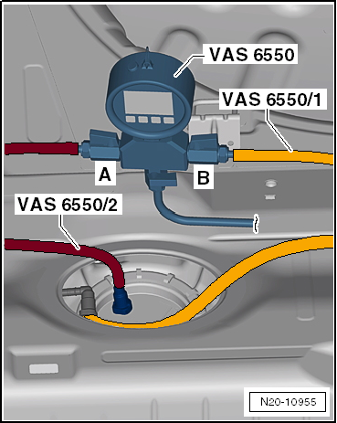
- Make sure that drain valve -C- on pressure gauge -VAS 6550--1- is closed.
- Shut-off valves -A- and -B- must be open on pressure gauge -VAS 6550--1-.
- Repeat the actuator test so that fuel pressure builds up.
- Slowly close shut-off valve -B-. The pressure must rise to at least 3.0 ... 3.3 bar. Once 3.0 ... 3.3 bar is reached, reopen the shut-off valve immediately!
If the nominal value is reached:
- Fuel pump OK. Check the fuel line to the engine compartment for possible restrictions (kinks) or blockages.
- Check the fuel line for leaks and damage.
If the nominal value is not reached:
- Remove the fuel delivery unit and check for contamination.
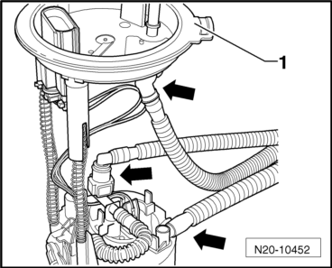
- Check that all hoses are connected -arrows-.
If no fault is found:
- Fuel pump faulty, replace the fuel delivery unit.
Check holding pressure
Required Special Tools, Test and Measuring Equipment and Auxiliary Items
- Pressure gauge -VAS 6550-
- Release Wedge -3409-
- Vehicle diagnostic tester
Test conditions:
- Power supply OK.
- Fuel pressure OK.
- Observe safety precautions.
- Observe cleanliness rules.

WARNING!
The fuel supply line is under pressure! Wear safety goggles and protective clothing to avoid injury and skin contact. Before loosening hose connections, place a rag around the connection point. Then relieve pressure by carefully pulling off the hose.
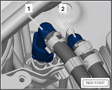
- Pull off supply line -1- (black) and catch escaping fuel with a rag. Disconnect quick-connect couplings.

WARNING!
The fuel line is under pressure!
Risk of eye and skin injury from fuel.
Wear safety goggles and protective clothing to avoid injury and skin contact. Before loosening hose connections, place a cleaning rag around the connection point. Then relieve pressure by carefully opening the connection point.
- Catch the escaping fuel with a shop rag.
- Connect the pressure gauge -VAS 6550- with adapter -VAS 6550/1- and -VAS 6550/2- to the fuel supply line.
- Connect hose line -VAS 6550/1- to the fuel supply line to the engine.
- Connect hose line -VAS 6550/2- to connection -A- of the pressure gauge -VAS 6550-.
- Connect the fuel line to the fuel tank to the pressure gauge -VAS 6550- using hose line -VAS 6550/2-.
- Check that the quick connectors are firmly seated by pulling against them!
Test procedure:
- Connect the vehicle diagnostic tester.

Note
- The fuel pump is now activated so that fuel pressure builds up.
- If the actuator test is to be carried out several times in succession, it may be necessary to start the engine briefly before repeating the actuator test.
- Read the fuel pressure on the pressure gauge.
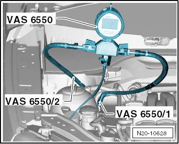
- Make sure that drain valve -C- on pressure gauge -VAS 6550--1- is closed.
- Shut-off valves -A- and -B- must be open on pressure gauge -VAS 6550--1-.
- Connect the vehicle diagnostic tester.
- On the display, press the buttons in sequence.
- Vehicle self-diagnosis
- Engine electronics
- Actuator test
- Electric fuel pump
- Button

Note
The fuel pump is now activated so that fuel pressure builds up.
- Read the fuel pressure on the pressure gauge.
- Nominal value: 3.0 ... 3.3 bar.
- Note the pressure drop on the pressure gauge. The pressure must not drop by more than 1.0 bar after 10 minutes.
If the pressure drops:
- Check all fuel lines for leaks and damage.
If no fault is found:
- Make sure that drain valve -C- on pressure gauge -1- is closed.
- Shut-off valves -A- and -B- on pressure gauge -1- are open.
- Activate the fuel pump with the actuator test so that fuel pressure builds up.
- Once the pressure has built up, immediately close shut-off valve -B- on the pressure gauge. The lever then points across the flow direction.
If the pressure now drops again (leak on the fuel tank side):
The leak is to be found on the fuel tank side. Proceed as follows.
If the pressure no longer drops (leak on the engine side):

Note
The leak is to be found on the engine side. Repeat the holding pressure test. This time, however, close shut-off valve -A- to determine whether there is actually a leak on the engine side.
If there is a leak on the engine side.
- Check the fuel lines externally for leaks.
- Check the fuel rail and the fuel injectors externally for leaks.
If no fault is found:
- Check the fuel injectors for leaks.
Check holding pressure at the underbody:
Check holding pressure at the underbody coupling point. Proceed as follows:

WARNING!
The fuel line is under pressure!
Risk of eye and skin injury from fuel.
Wear safety goggles and protective clothing to avoid injury and skin contact. Before loosening hose connections, place a cleaning rag around the connection point. Then relieve pressure by carefully opening the connection point.
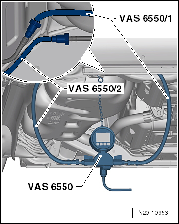
- Disconnect fuel supply line -2-. Separate the quick-connect couplings.

- Connect the pressure gauge -VAS 6550- with adapter -VAS 6550/1- and -VAS 6550/2- to the quick-connect couplings of the fuel supply line.
- Connect hose line -VAS 6550/1- between the fuel line to the engine compartment and shut-off valve -B-.
- Connect hose line -VAS 6550/2- between the fuel line to the fuel tank and shut-off valve -A-.
- Make sure that the drain valve is closed and the shut-off valves are open.
- Activate the fuel pump with the actuator test so that fuel pressure builds up.
- Once the pressure has built up, immediately close shut-off valve -B- on the pressure gauge. The lever then points across the flow direction.
If the pressure no longer drops:

Note
The leak is to be found in the fuel line between the underbody coupling point and the coupling point in the engine compartment.
If the pressure drops again:
Check holding pressure at the fuel pump module. Proceed as follows:
- Remove the seat bench → Body Assembly Work, Interior.
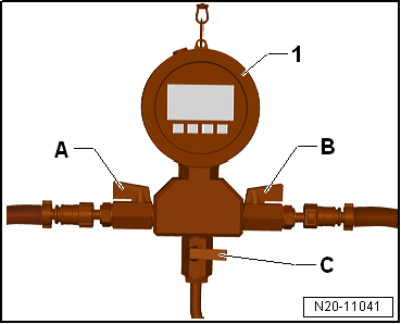
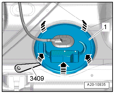
- Unclip cover -1- from the retaining clips using demolding wedge -3409- -arrows-.
- Check that connector -1- is seated firmly by pulling on the connector without pressing the locking tab. If the connector was not plugged in correctly, repeat the fuel pump function check.

WARNING!
The fuel line is under pressure!
Risk of eye and skin injury from fuel.
Wear safety goggles and protective clothing to avoid injury and skin contact. Before loosening hose connections, place a cleaning rag around the connection point. Then relieve pressure by carefully opening the connection point.
- Disconnect fuel supply line -2- from the fuel delivery unit. Separate the quick-connect couplings.
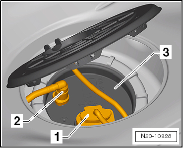
- Connect pressure gauge -VAS 6550- with adapters -VAS 6550/1- and -VAS 6550/2- between the fuel line and the fuel pump module.
- Connect hose line -VAS 6550/1- between the fuel line and shut-off valve -B-.
- Connect hose line -VAS 6550/2- between the fuel delivery unit and shut-off valve -A-.
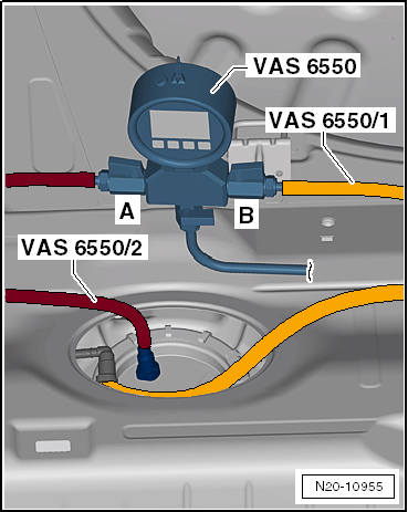
- Make sure that drain valve -C- is closed and shut-off valves -A- and -B- are open.
- Activate the fuel pump with the actuator test so that fuel pressure builds up.
- Once the pressure has built up, immediately close shut-off valve -B- on the pressure gauge. The lever then points across the flow direction.
If the pressure no longer drops:

Note
The leak is to be found in the fuel line between the underbody coupling point and the fuel pump module.
If the pressure drops again:
- Remove fuel pump.
- Check that all hoses are connected -arrows-.
- Check the fuel lines for leaks and damage.
If no fault is found:
- Replace the fuel delivery unit.

Check fuel delivery rate
Required Special Tools, Test and Measuring Equipment and Auxiliary Items
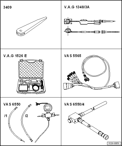
- Release Wedge -3409-
- Remote control to V.A.G 1348 -V.A.G 1348/3A-
- Multimeter, e.g. hand-held multimeter -V.A.G 1526E-
- Adapter for measuring technology/DSO (5-pin) -VAS 5565-
- Pressure gauge -VAS 6550-
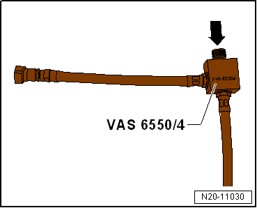
- Pressure regulating valve -VAS 6550/4-
- Vehicle diagnostic tester
- Measuring container min. 3 l

Note
- Disconnect plug-in connectors.
- If driveability faults occur with the fuel tank at most 1/4 full, perform the fuel delivery rate test with the fuel tank at 1/4 full or at a lower level.
- Observe safety precautions.
- Observe cleanliness rules.
- Battery voltage at least 11.5 V, connect battery charger if necessary → Electrical System.
- Control unit for fuel pump -J538- OK → Vehicle Diagnostic Tester.
- Fuel level in the fuel tank is above reserve.
- Power supply OK.
- Fuel pressure OK.
- Remove the seat bench → Body Assembly Work, Interior.
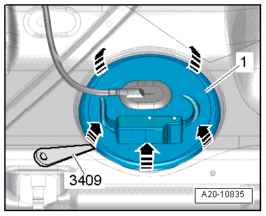
- Unclip cover -1- from the retaining clips using demolding wedge -3409- -arrows-.
- Check that connector -1- is seated firmly by pulling on the connector without pressing the locking tab. If the connector was not plugged in correctly, repeat the fuel pump function check.
- Unlock connector -1- and disconnect it.
- Check the contacts on the connector and on the fuel pump module for damage.
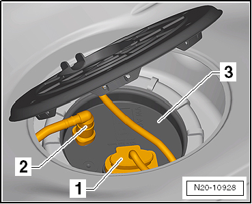
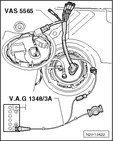
- Connect adapter for measuring technology/DSO (5-pin) -VAS 5565- to the connector and to the fuel pump module.
- Connect remote control -V.A.G 1348/3A- to adapter -VAS 5565- and to the positive battery terminal in the engine compartment.

Note
This step is only used to run the fuel pump with the engine off.

WARNING!
The fuel line is under pressure!
Risk of eye and skin injury from fuel.
Wear safety goggles and protective clothing to avoid injury and skin contact. Before loosening hose connections, place a cleaning rag around the connection point. Then relieve pressure by carefully opening the connection point.
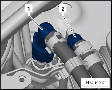
- Pull off supply line -1- (black) and catch escaping fuel with a rag. Disconnect quick-connect couplings.
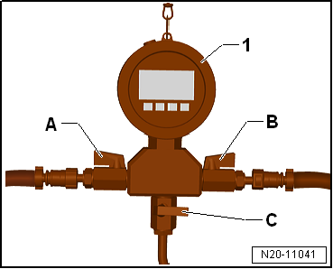
- Connect pressure gauge -VAS 6550- with hose line -VAS 6550/2- to the fuel supply line from the fuel tank.
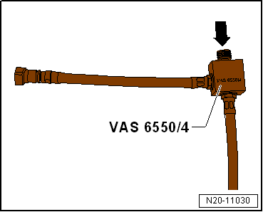
- Connect pressure regulating valve -VAS 6550/4- to connection -B- of pressure gauge -VAS 6550-.
- Hold the open end of the hose from pressure regulating valve -VAS 6550/4- in a measuring container.

- Make sure that drain valve -C- on pressure gauge -1- is closed.
- Shut-off valves -A- and -B- on pressure gauge -1- are open.
- Press remote control -V.A.G 1348/3A-.

Note
Fuel pump for pre-delivery -G6- is being activated!
- Use the adjusting wheel on the pressure regulating valve arrow to set a back pressure of 3.0 bar.

WARNING!
Risk of spraying! Wear safety goggles and protective clothing to avoid injury and skin contact. Hold the container in front of the open connection of pressure gauge -VAS 6550-.
- Do not change the position of the adjusting wheel now.
- Empty the measuring container.
- The fuel delivery rate of the fuel pump depends on the battery voltage. Therefore, additionally connect multimeter -V.A.G 1715- to terminals -1- and -5- of the adapter for measuring technology/DSO (5-pin) -VAS 5565-.
- Operate the remote control for 60 seconds and measure the voltage at the fuel pump during this time.
- Compare the delivered fuel quantity with the nominal value.
Minimum delivery rate cm 3/60 s
Voltage at the fuel pump with engine off and pump running: 12 volts.
Nominal value: approx. 1050 cm 3/60 s.
If the nominal value is not reached:
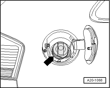
- Open the fuel filler flap.
- Remove the filler cap -arrow- from the fuel filler neck.
- Repeat the fuel delivery rate test.
- If the fuel delivery rate is now reached, check the fuel tank ventilation.
If the nominal value is not reached:
- Check the fuel lines for possible restrictions (kinks) or blockages.
- Check the fuel lines for leaks and damage.
If no fault is found:
Check fuel delivery rate at the underbody coupling point. Proceed as follows.
Check fuel delivery rate at the underbody coupling point:
- Disconnect fuel supply line -2-. Separate the quick-connect couplings.

WARNING!
The fuel line is under pressure!
Risk of eye and skin injury from fuel.
Wear safety goggles and protective clothing to avoid injury and skin contact. Before loosening hose connections, place a cleaning rag around the connection point. Then relieve pressure by carefully opening the connection point.
- Catch the escaping fuel with a shop rag.
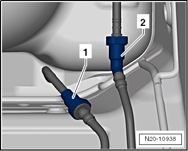
- Connect pressure gauge -VAS 6550- with hose line -VAS 6550/2- to shut-off valve -A-.
- Connect pressure gauge -VAS 6550- with hose line -VAS 6550/2- to the fuel supply line -1- from the fuel tank.
- Connect pressure regulating valve -VAS 6550/4- to connection -B- of pressure gauge -VAS 6550-.
- Hold the open end of the hose from pressure regulating valve -VAS 6550/4- in a measuring container.
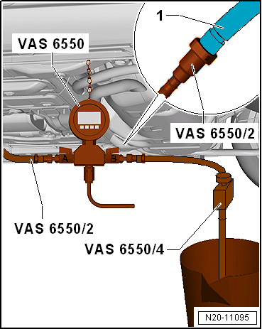
- Make sure that drain valve -C- on pressure gauge -VAS 6550--1- is closed.
- Shut-off valves -A- and -B- must be open on pressure gauge -VAS 6550--1-.
- Repeat test.
If the nominal value is reached:
- Check the fuel lines to the engine for possible restrictions (kinks) or blockages.
- Check the fuel lines to the engine for leaks and damage.
If the nominal value is still not reached:
Check fuel delivery rate at the fuel pump module. Proceed as follows:

WARNING!
The fuel line is under pressure!
Risk of eye and skin injury from fuel.
Wear safety goggles and protective clothing to avoid injury and skin contact. Before loosening hose connections, place a cleaning rag around the connection point. Then relieve pressure by carefully opening the connection point.
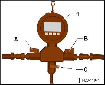
- Disconnect fuel line -2-. Separate the plug-in couplings.
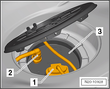
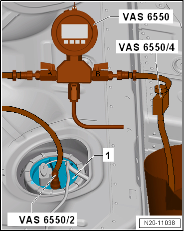
- Connect pressure gauge -VAS 6550- with hose line -VAS 6550/2- to fuel pump module -1-.
- Connect hose line -VAS 6550/2- to connection -A- of pressure gauge -VAS 6550-.
- Connect pressure regulating valve -VAS 6550/4- to connection -B- of pressure gauge -VAS 6550-.
- Hold the open end of the hose from pressure regulating valve -VAS 6550/4- in a measuring container.
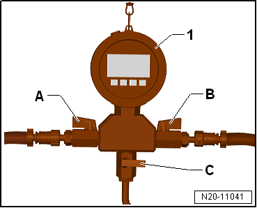
- Make sure that drain valve -C- on pressure gauge -1- is closed.
- Shut-off valves -A- and -B- on pressure gauge -1- are open.
- Press remote control -V.A.G 1348/3A-.

Note
Fuel pump for pre-delivery -G6- is being activated!
- Use the adjusting wheel on the pressure regulating valve arrow to set a back pressure of 3.0 bar.
- Do not change the position of the adjusting wheel now.
- Empty the measuring container.
- Repeat the fuel delivery rate test at the fuel pump module.
If the minimum delivery rate is now reached:
- Check the fuel lines for possible restrictions (kinks) or blockages.
If the minimum delivery rate is still not reached:
- Remove fuel pump.
- Check the filter screen for contamination.
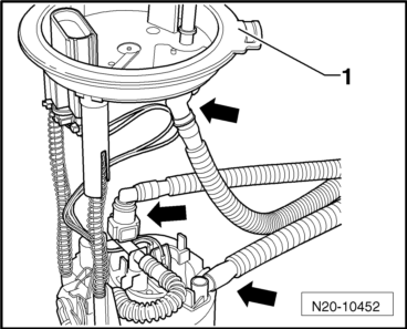
- Check that all hoses are connected -arrows-.
Only if no fault has been found so far:
- Replace the fuel delivery unit.
The fuel delivery rate has been reached, yet a fault in the fuel supply is suspected:
- Check the current draw of the fuel pump.
Check current draw
Required Special Tools, Test and Measuring Equipment and Auxiliary Items
- Release Wedge -3409-
- Multimeter, e.g. hand-held multimeter -V.A.G 1526E-
- Current clamp, e.g. current clamp -V.A.G 1526B/2-
- Adapter for measuring technology/DSO (5-pin) -VAS 5565-

Note
- Plug-in connectors must audibly lock into place when engaged.
- When installing plug-in connectors, observe the color coding!
- Check that the plug-in connector is secure by pulling against it!
- Disconnect plug-in connectors.
- Observe safety precautions.
- Observe cleanliness rules.
- Battery charger is connected.
- Power supply OK.
- Remove the seat bench → Body Assembly Work, Interior.
- To do so, unclip cover -1- at the retaining lugs using removal wedge -3409- -arrows-.
- Check the plug connection -1- for a secure fit by pulling on the connector without pressing the locking tab. If the connector was not fully engaged, it may have caused a fault.
- Unlock connector -1- and disconnect it.
- Check the contacts on the connector and on the fuel pump module for damage.
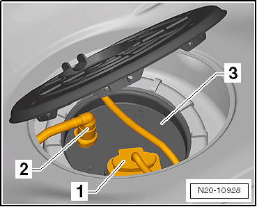
- Plug adapter for measuring technology/DSO (5-pin) -VAS 5565- into the connector and the fuel pump unit.
- Connect current clamp -A- to the red cable, labeled "Current clamp," of the measurement/DSO adapter (5-pin) -VAS 5565-.
- Start the engine and let it run at idle.
- Measure the current draw of the fuel pump.
- Specified value: max. 8 amps

Note
- The fuel pump's inrush current may briefly exceed the specified value when the engine starts.
- If the fuel system fault only occurs intermittently, the test can also be carried out during a road test. A second person is required for this.
If the current draw is exceeded:
- Remove fuel pump.
- Check the filter screen for contamination.
Test OK:
- Fuel pump faulty, replace the fuel delivery unit.