Removing and installing steering column
Removing and installing steering column, electric steering column, left-hand drive, up!
Required Special Tools, Test and Measuring Equipment and Auxiliary Items
Torque Wrench -V.A.G 1331-
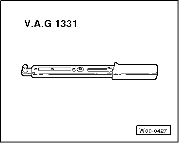
Torque Wrench -V.A.G 1332-
Removing

WARNING!
Before working on the electrical system and removing the steering wheel, the following conditions must be met:
- Unscrew the ground strap from the battery → Electrical System.
- The wheels must be in the straight-ahead position.
Failure to observe these notes may cause the airbag system to fail during later operation!
- Set the wheels to the straight-ahead position.
- Pull the lever on the side of the steering column downward.
- Swivel the steering column down as far as possible and pull it out.
- Push the lever on the side of the steering column back up.
- Remove driver airbag unit → Body Assembly Work Interior.
- Remove steering wheel.
- Remove steering column combination switch -E595- → Electrical System.
- Remove lower steering column trim.
- Remove upper steering column trim.
- Remove dash panel trim under the steering column → Body Assembly Work Interior.

- Unclip wiring harness -1- from the steering column -arrows-.
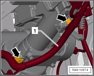
- Pull connector -1- off the steering lock.
- Unscrew bolt -2- and unscrew ground lead for steering column -3-.
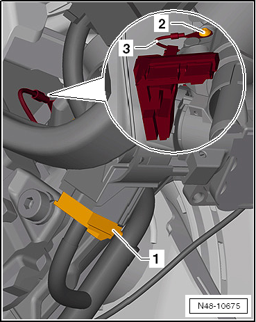
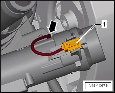
- Pull connector -1- off the immobilizer reader coil -D2-.
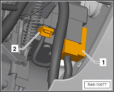
- Pull the lead out of the holder -arrow-.

- Pull connectors -1- and -2- off the steering column electronics control unit -J500-.
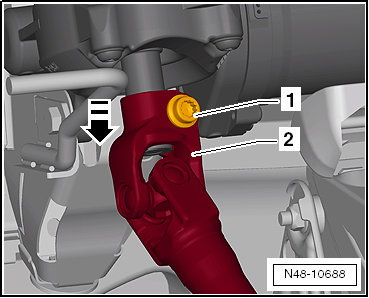
- Unscrew bolt -1-.
- Pull intermediate shaft for steering column -2- off the steering column in the -direction of arrow- and set it aside.

- Unscrew nut -1-.
- Pull out bolt -2- and remove crash strut -3-.

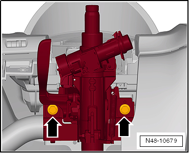
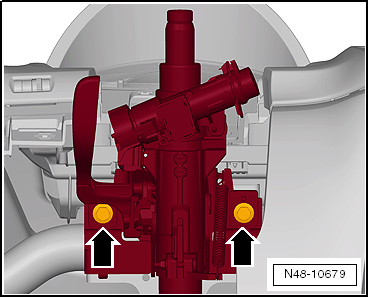
- Unscrew bolts -arrows- of the steering column and hold the steering column.
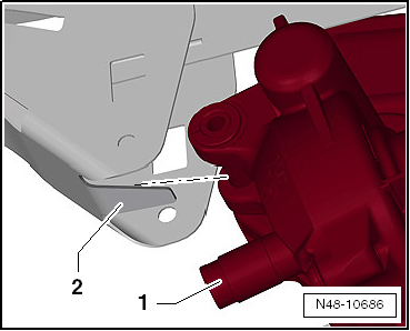
- Lower steering column -1- slightly and carefully pull it forward out of guide -2- on the cross member.

Caution!
Be sure to handle and transport the steering column correctly.
Installing
- Fit new installation aid to the steering column.

Note
When installing the steering column, the installation sequence for the mounting bolts must be strictly observed.

- Carefully insert steering column -1- into guide -2- on the cross member.
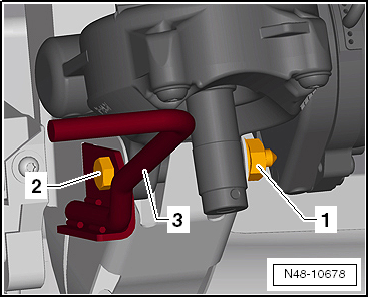
- Insert bolt -2- with crash strut -3-.
- Start nut -1- by hand.
- Swivel steering column up and engage it in the cross member.
The lugs -arrows- of the installation aid must engage in the cross member.

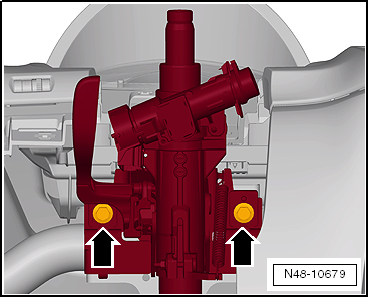
- Start bolts -arrows- of the steering column by hand.
- Tighten bolt -2-.

- Tighten bolts -arrows- of the steering column.
- Fit intermediate shaft for steering column -2- to the steering column in the opposite direction of the -arrow- and bolt it on with a new bolt -1- to the specified tightening torque.
- Connect connectors -1- and -2- to steering column electronics control unit -J500-.

- Connect connector -1- to the immobilizer reader coil -D2-.
- Insert lead into holder -arrow-.
- Bolt on ground lead for steering column -3- with bolt -2-.
- Connect connector -1- to the steering lock.

- Clip wiring harness -1- to the steering column -arrows-.
- Install dash panel trim under the steering column → Body Assembly Work Interior.
- Install steering column combination switch -E595- → Electrical System.
- Install upper steering column trim.
- Install lower steering column trim.
- Install steering wheel.
- Install airbag unit → Body Assembly Work Interior.
- After replacing, or removing and installing the steering column, the steering must be readjusted → Vehicle Diagnostic Tester.

WARNING!
Make sure no persons are inside the vehicle while the battery is being connected!
- Connect ground strap to the battery → Electrical System.

Tightening torques

Removing and installing steering column, electric steering column, right-hand drive
Required Special Tools, Test and Measuring Equipment and Auxiliary Items
- Torque Wrench -V.A.G 1331-

- Torque Wrench -V.A.G 1332-
Removing
Only up!

WARNING!
Before working on the electrical system and removing the steering wheel, the following conditions must be met:
- Unscrew the ground strap from the battery → Electrical System.
- The wheels must be in the straight-ahead position.
Failure to observe these notes may cause the airbag system to fail during later operation!
Only e-up!

WARNING!
Before working on the electrical system and removing the steering wheel, the following conditions must be met:
- Risk of injury! Observe warnings and safety regulations → Electrical System General Information.
- Unscrew the ground strap from the battery → Electrical System.
- The wheels must be in the straight-ahead position.
Failure to observe these notes may cause the airbag system to fail during later operation!
Continuation for all vehicles
- Set the wheels to the straight-ahead position.
- Pull the lever on the side of the steering column downward.
- Swivel the steering column down as far as possible and pull it out.
- Push the lever on the side of the steering column back up.
- Remove driver airbag unit → Body Assembly Work Interior.
- Remove steering wheel.
- Remove steering column combination switch -E595- → Electrical System.
- Remove lower steering column trim.
- Remove upper steering column trim.
- Remove dash panel trim under the steering column → Body Assembly Work Interior.

- Unclip wiring harness -1- from the steering column -arrow-.

- Press lug -2- of holder -1- in the -direction of arrow A-.
- At the same time, slide holder -1- out of the guide on the steering column in the -direction of arrow B-.

- Pull connector -1- off the steering lock.
- Unscrew bolt -2- and unscrew ground lead for steering column -3-.

- Pull connector -1- off the immobilizer reader coil -D2-.
- Pull the lead out of the holder -arrow-.

- Pull connectors -1- and -2- off the steering column electronics control unit -J500-.

- Unscrew bolt -1-.
- Pull intermediate shaft for steering column -2- off the steering column in the -direction of arrow- and set it aside.

- Unscrew bolt -1- and remove crash strut -2-.

- Unscrew bolts -arrows- of the steering column and hold the steering column.

- Lower steering column -1- slightly and carefully pull it forward out of guide -2- on the cross member.

Caution!
Be sure to handle and transport the steering column correctly.
Installing
- Fit new installation aid to the steering column.

Note
When installing the steering column, the installation sequence for the mounting bolts must be strictly observed.

- Carefully insert steering column -1- into guide -2- on the cross member.
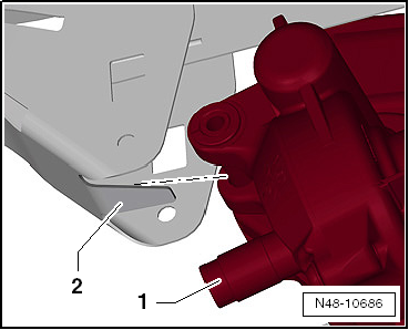
- Fit crash strut -2- and tack it in place with bolt -1-.
- Swivel steering column up and engage it in the cross member.
The lugs -arrows- of the installation aid must engage in the cross member.

- Start bolts -arrows- of the steering column by hand.

- Tighten bolt -1-.

- Tighten bolts -arrows- of the steering column.

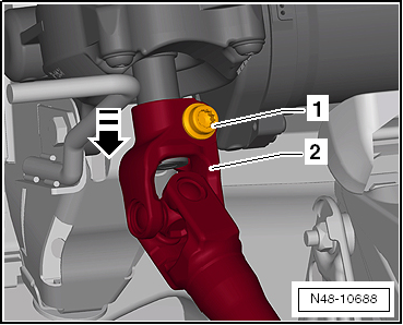
- Fit intermediate shaft for steering column -2- to the steering column in the opposite direction of the -arrow- and bolt it on with a new bolt -1- to the specified tightening torque.
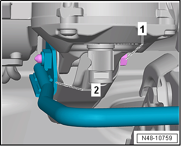
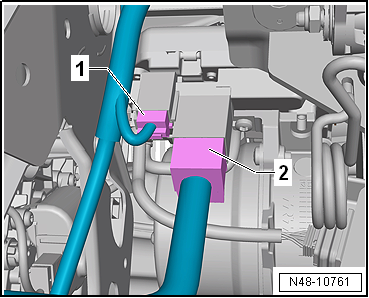
- Connect connectors -1- and -2- to steering column electronics control unit -J500-.
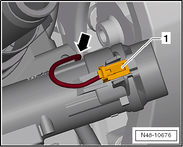
- Connect connector -1- to the immobilizer reader coil -D2-.
- Insert lead into holder -arrow-.
- Bolt on ground lead for steering column -3- with bolt -2-.
- Connect connector -1- to the steering lock.
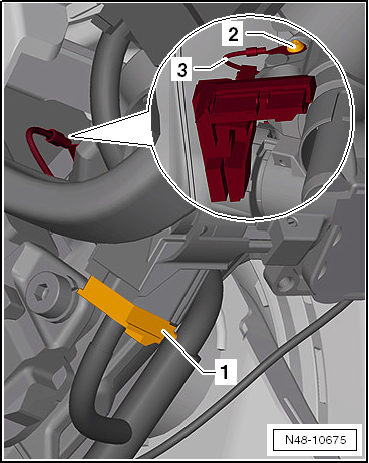
- Slide holder -1- into the guide on the steering column opposite to the -direction of arrow B-.
- Lug -2- of holder -1- must engage on the steering column.

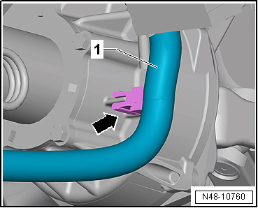
- Clip wiring harness -1- to the steering column -arrow-.
- Install dash panel trim under the steering column → Body Assembly Work Interior.
- Install steering column combination switch -E595- → Electrical System.
- Install upper steering column trim.
- Install lower steering column trim.
- Install steering wheel.
- Install airbag unit → Body Assembly Work Interior.
- After replacing, or removing and installing the steering column, the steering must be readjusted → Vehicle Diagnostic Tester.

WARNING!
Make sure no persons are inside the vehicle while the battery is being connected!
Only up!
- Connect ground strap to the battery → Electrical System.
Only e-up!

WARNING!
- Risk of injury! Observe warnings and safety regulations → Electrical System General Information.
- Connect ground strap to the battery → Electrical System.
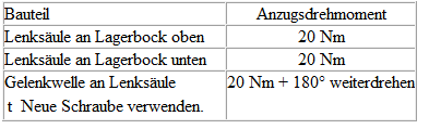
Tightening torques
Removing and installing steering column, steel steering column
Required Special Tools, Test and Measuring Equipment and Auxiliary Items
- Torque Wrench -V.A.G 1331-

- Torque Wrench -V.A.G 1332-
Removing
Only up!

WARNING!
Before working on the electrical system and removing the steering wheel, the following conditions must be met:
- Unscrew the ground strap from the battery → Electrical System.
- The wheels must be in the straight-ahead position.
Failure to observe these notes may cause the airbag system to fail during later operation!
Only e-up!

WARNING!
Before working on the electrical system and removing the steering wheel, the following conditions must be met:
- Risk of injury! Observe warnings and safety regulations → Electrical System General Information.
- Unscrew the ground strap from the battery → Electrical System.
- The wheels must be in the straight-ahead position.
Failure to observe these notes may cause the airbag system to fail during later operation!
Continuation for all vehicles
- Set the wheels to the straight-ahead position.
- Remove driver airbag unit → Body Assembly Work Interior.
- Remove steering wheel.
- Remove steering column combination switch -E595- → Electrical System.
- Remove lower steering column trim.
- Remove upper steering column trim.
- Remove dash panel trim under the steering column → Body Assembly Work Interior.

- Unclip wiring harness -1- from the steering column -arrows-.

- Pull connector -1- off the steering lock.
- Unscrew bolt -2- and unscrew ground lead for steering column -3-.

- Pull connector -1- off the immobilizer reader coil -D2-.
- Pull the lead out of the holder -arrow-.

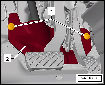
- Unscrew bolts -1- and remove footwell trim -2-.

- Unscrew bolt -1- from universal joint -2- and pull universal joint off in the -direction of arrow-.

- Unscrew nut -1-.
- Pull out bolt -2- and remove crash strut -3-.

- Unscrew bolts -arrows- of the steering column and hold the steering column.
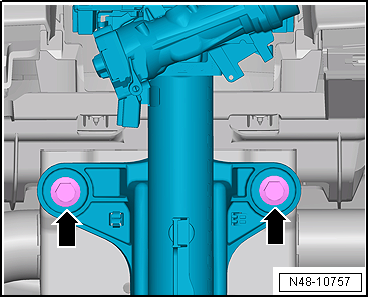
- Lower steering column -1- slightly and carefully pull it forward out of guide -2- on the cross member.
Installing
- Fit new installation aid to the steering column.

Note
When installing the steering column, the installation sequence for the mounting bolts must be strictly observed.

- Carefully insert steering column -1- into guide -2- on the cross member.
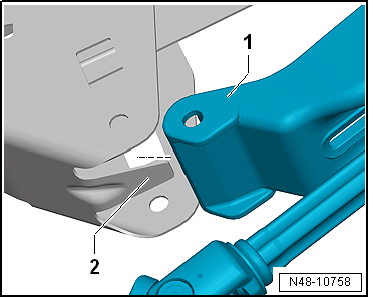
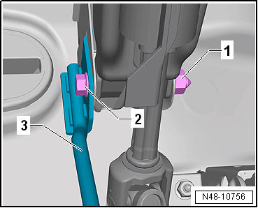
- Insert bolt -2- with crash strut -3-.
- Start nut -1- by hand.

- Swivel steering column up and engage it in the cross member.
The lugs -arrows- of the installation aid must engage in the cross member.

- Start bolts -arrows- of the steering column by hand.
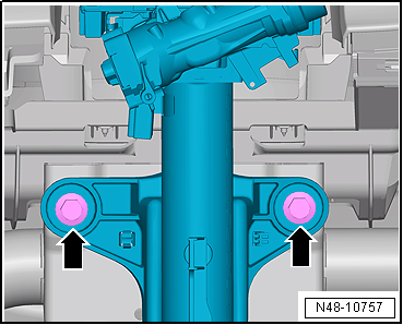
- Tighten bolt -2-.
- Tighten bolts -arrows- of the steering column.

- Fit universal joint -2- to the steering gear in the opposite direction of the -arrow- and bolt it on with a new bolt -1- to the specified tightening torque.

- Connect connector -1- to the immobilizer reader coil -D2-.
- Insert lead into holder -arrow-.
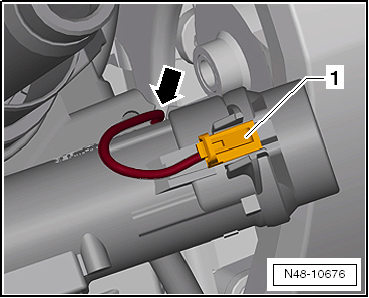
- Bolt on ground lead for steering column -3- with bolt -2-.
- Connect connector -1- to the steering lock.

- Clip wiring harness -1- to the steering column -arrows-.
- Install dash panel trim under the steering column → Body Assembly Work Interior.
- Install steering column combination switch -E595- → Electrical System.
- Install upper steering column trim.
- Install lower steering column trim.
- Install steering wheel.
- Install airbag unit → Body Assembly Work Interior.

WARNING!
Make sure no persons are inside the vehicle while the battery is being connected!
Only up!
- Connect ground strap to the battery → Electrical System.
Only e-up!

WARNING!
- Risk of injury! Observe warnings and safety regulations → Electrical System General Information.
- Connect ground strap to the battery → Electrical System.

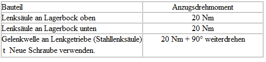
Tightening torques
Handling and transporting the steering column

WARNING!
- Correct handling of the steering column must be strictly observed.
- Incorrect handling of the steering column can damage the steering column and thus create a safety risk.
Correct handling and transport of the steering column
- Transport the steering column with both hands.
- Hold the steering column at the outer column tube at the top and in the area below the gear box.

Incorrect handling of the steering column with safety risk
The following handling will damage the universal joint bushings and the lower steering column bearing of the steering column:
- Transporting the steering column with one hand on the intermediate shaft.
- Bending the joints over 90º.
The following handling can damage the steering column:

- Lifting and carrying by the clamp lever.

- Lifting and carrying by the weight compensation spring.
- Lifting and carrying by the motor/control unit for steering column electronics -J500-.
- Lifting and carrying by the wiring of the control unit for steering column electronics -J500-.

Removing and installing control unit for steering column electronics -J500-
Required Special Tools, Test and Measuring Equipment and Auxiliary Items
- Torque wrench -V.A.G 1410-
Carry out the following work:
Removing
- Remove steering column.

- Disconnect connectors -1- from control unit for steering column electronics -J500--2-.

- Pry off cover -1-.

- Unscrew bolts -1-.
- Unscrew bolts -2- and remove control unit for steering column electronics -J500--3-.

Note
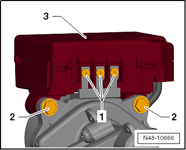
- After removing the control unit for steering column electronics -J500-, do not place the steering column on the contacts -arrows-.
- This will destroy the contacts, and the steering column must then be replaced complete.
Installing

- Correctly position control unit for steering column electronics -J500--1- onto the contacts -arrows-.

- Install bolts -1-.
- Install bolts -2- and tighten to the specified torque.
- Tighten bolts -1- to the specified torque.
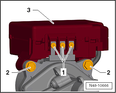
- Fit new cover -1- and engage it -arrows-.
- Install steering column.
- After replacing, or removing and installing the control unit for steering column electronics, the steering must be readjusted → Vehicle diagnostic tester.
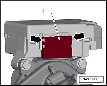
Tightening torques

Removing and installing steering intermediate shaft
Required Special Tools, Test and Measuring Equipment and Auxiliary Items
- Torque Wrench -V.A.G 1331-
Carry out the following work:
Removing

- Unscrew bolts -1- and remove footwell trim -2-.
- Unscrew bolt -arrow- from universal joint -1- and pull universal joint off in direction of -arrow-.

- Unscrew bolt -1-.
- Pull steering column universal joint -2- off the steering column in the -arrow direction- and remove.
Installing
- Installation is carried out in the reverse order.

Tightening torques
