Wheel installation
Fitting the wheel
Installing wheel, Volkswagen installation notes
Vehicles with tire pressure sensor
If the wheels are changed (e.g. changing from summer to winter tires), the wheel electronics transmit data as soon as the speed of the new wheels exceeds 25 km/h. The identification numbers of the new wheel electronics are automatically detected and read in by the control unit.
In addition, the acceleration data is checked against the vehicle speed. This process takes approx. 7 minutes.
The tire pressure monitoring control unit -J502- must first enter learning mode before it can automatically learn the wheel electronics.
For this, the vehicle must stand for 20 minutes. After a detected tire puncture, this time is 5 minutes.
If the standing time is not observed and the control unit is therefore not yet in learning mode, the system detects a radio interference and will only automatically learn the wheel electronics after a standing time of 20 minutes.

Note
- When changing wheels, note that only wheel/tire combinations approved by the vehicle manufacturer may be fitted, with the tire inflation pressure specified on the fuel filler flap label.
- If wheel/tire combinations not approved are fitted, they must have an expert report from a Technical Inspection Authority for the respective vehicle, and a 2nd wheel set must be learned via the → Vehicle diagnostic tester.
- Learning remains necessary if the tire inflation pressure deviates from the tire inflation pressure specified on the fuel filler flap label.
Tire sets with other target tire inflation pressures
If a vehicle is fitted with tires that require target tire inflation pressures different from those shown on the fuel filler flap label, this tire set (wheel set 2) can also be monitored by the tire pressure monitoring system.
Target tire inflation pressures for wheel set 2 must be specified to the system using the → Vehicle diagnostic tester.
The wheel electronics of the wheels of wheel set 2 are not automatically detected and learned by the tire pressure monitoring system (unlike the wheel electronics of a wheel set with wheel/tire combinations approved by the vehicle manufacturer).
To switch to wheel set 2, the following work must be carried out:
- Read the identification numbers (IDs) of the wheel electronics (tire pressure sensors) before installation.
- Switch the TPMS to wheel set 2.
- Enter the required target tire inflation pressures and the IDs of the wheel electronics into the system.
Continuation for all vehicles

Note
The key size of the supplied adapter for the wheel bolts may differ from the key size of the respective master set.
Required Special Tools, Test and Measuring Equipment and Auxiliary Items
- Torque Wrench -V.A.G 1332-
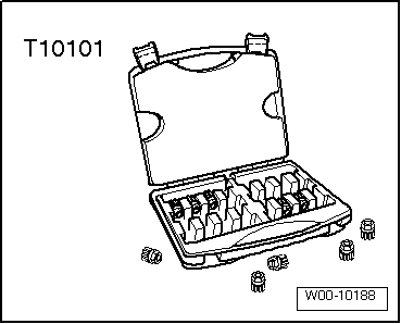
- Master set for wheel bolts -T10101-

- Master set for wheel bolts -T10101 A-
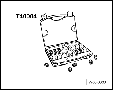
- Master set for wheel bolts -T40004-
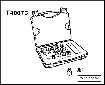
- Master set for wheel bolts -T40073-
- Wax spray -D 322 000 A2-
- Optimol TA paste -G 052 109 A2-
- Switch the ignition off.

WARNING!
The wheel bolts and wheels are only secure if you follow the checks and instructions below.

Note
On vehicles with a tire pressure warning display, the tire pressure warning display must be recalibrated after removing and installing one or more wheels → Vehicle diagnostic tester.
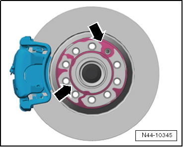
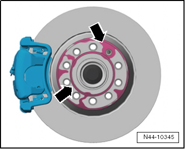
- Check that the contact surfaces -arrows- on the brake disc are free of corrosion and dirt.
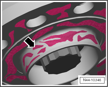
- Check that the contact surface -arrow- of the brake disc centering seat is free of corrosion and dirt.
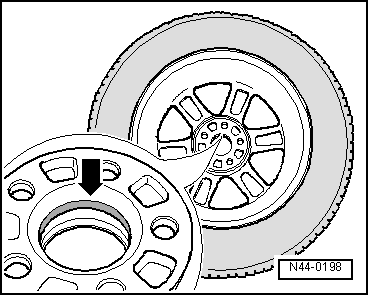
- Check that the contact surface -arrow- on the inner side of the wheel (rim) and the centering seat in the rim are free of corrosion and dirt.
- The ball seats * in the wheel bolt holes and the threads of the wheel bolts must also be free of corrosion, dirt, oil or grease.
* A ball seat is the curved surface of a spherical segment.

- Check that the wheel bolts can be screwed in easily by hand. The thread of the wheel bolt must not contact the bore in the brake disc -arrow-.
If the thread of the wheel bolt contacts the hole -arrow-, turn the brake disc accordingly.
If necessary, remove dirt and corrosion:
- Oil or grease from the contact surfaces
- Remove oil or grease from the threads in the wheel hub.
- Remove oil or grease from the threads of the wheel bolts.

WARNING!
Heavily corroded, stiff-running and/or damaged wheel bolts must be replaced!
Applies to light alloy and steel wheels.
When changing wheels, the wheel centering seat should be waxed with wax spray to prevent corrosion between the wheel centering seat and the rim → Electronic Parts Catalog "ETKA.".
- Remove wheel.
- Thoroughly clean the wheel centering seat on the wheel hub and the centering of the rim.
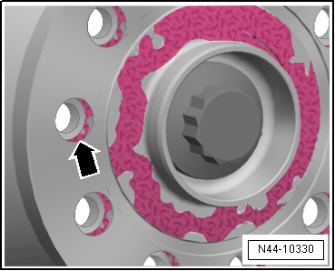
- Apply the wax to the centering area -arrow- with a brush.
Make sure to apply wax only to the centering -arrow- and not to the contact surface of the rim. Otherwise, the brake will become contaminated during driving, resulting in poor braking performance.

WARNING!
Wheel bolts, contact surfaces of wheel/wheel hub and threads in the wheel hub must not be waxed. Never treat wheel bolt threads with lubricants or anti-corrosion agents!
- When mounting the wheel, tighten all wheel bolts evenly by hand.
- Tighten the wheel bolts in a crisscross pattern to approx. 30 N·m.
- Lower the vehicle to the ground. Tighten all wheel bolts in a crosswise sequence to the specified tightening torque using the torque wrench.
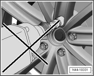
Do not use an impact wrench!

WARNING!
Do not use an impact wrench to screw in the wheel bolts!
Tightening torque
- → Suspension, axles, steering;
Install wheel, Audi installation notes
Vehicles with tire pressure sensor
If the wheels are changed (e.g. changing from summer to winter tires), the wheel electronics transmit data as soon as the speed of the new wheels exceeds 25 km/h. The identification numbers of the new wheel electronics are automatically detected and read in by the control unit.
In addition, the acceleration data is checked against the vehicle speed. This process takes approx. 7 minutes.
The tire pressure monitoring control unit -J502- must first enter learning mode before it can automatically learn the wheel electronics.
For this, the vehicle must stand for 20 minutes. After a detected tire puncture, this time is 5 minutes.
If the standing time is not observed and the control unit is therefore not yet in learning mode, the system detects a radio interference and will only automatically learn the wheel electronics after a standing time of 20 minutes.

Note
- When changing wheels, note that only wheel/tire combinations approved by the vehicle manufacturer may be fitted, with the tire inflation pressure specified on the fuel filler flap label.
- If wheel/tire combinations not approved are fitted, they must have an expert report from a Technical Inspection Authority for the respective vehicle, and a 2nd wheel set must be learned via the → Vehicle diagnostic tester.
- Learning remains necessary if the tire inflation pressure deviates from the tire inflation pressure specified on the fuel filler flap label.
Tire sets with other target tire inflation pressures
If a vehicle is fitted with tires that require target tire inflation pressures different from those shown on the fuel filler flap label, this tire set (wheel set 2) can also be monitored by the tire pressure monitoring system.
Target tire inflation pressures for wheel set 2 must be specified to the system using the → Vehicle diagnostic tester.
The wheel electronics of the wheels of wheel set 2 are not automatically detected and learned by the tire pressure monitoring system (unlike the wheel electronics of a wheel set with wheel/tire combinations approved by the vehicle manufacturer).
To switch to wheel set 2, the following work must be carried out:
- Read the identification numbers (IDs) of the wheel electronics (tire pressure sensors) before installation.
- Switch the TPMS to wheel set 2.
- Enter the required target tire inflation pressures and the IDs of the wheel electronics into the system.
Continuation for all vehicles

Note
The key size of the supplied adapter for the wheel bolts may differ from the key size of the respective master set.
Required Special Tools, Test and Measuring Equipment and Auxiliary Items
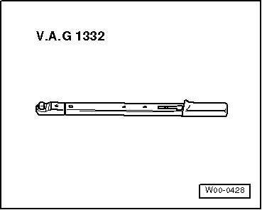
- Torque Wrench -V.A.G 1332-
- Master set for wheel bolts -T10101-
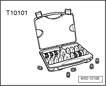
- Master set for wheel bolts -T10101 A-
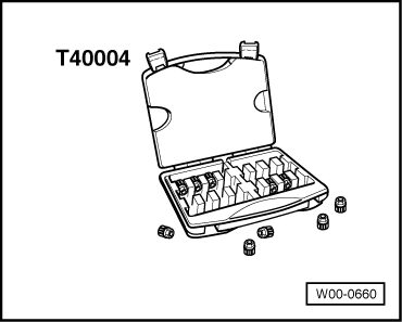
- Master set for wheel bolts -T40004-
- Master set for wheel bolts -T40073-
- Wax spray -D 322 000 A2-
- Optimol TA paste -G 052 109 A2-
- Switch the ignition off.

Caution!
On vehicles with ceramic brakes, the wheel must not drop onto the brake disc, as this will cause irreparable damage. To remove/install the wheel, turn the long installation pin into the uppermost position (12 o'clock) instead of the wheel bolts, and insert the short installation pin into the wheel bolt holes for support. This allows the wheel to slide on the installation aids when removing/installing it.

Note
- Only lift the vehicle at the designated lifting points.
- On vehicles with light alloy wheels, do not pry off the cover caps with a screwdriver; only use the special tool provided for this purpose (pull-off hook in the on-board tool kit).
- To loosen the wheel bolts, use socket inserts with the correct socket size. Damaged socket inserts must not be reused.
- Do not use impact wrenches to loosen anti-theft wheel bolts (lockable wheel bolts).
- Do not contaminate the wheel bolts.

DANGER!
The wheel bolts and wheels are only secure if you follow the checks and instructions below.
The following checks/instructions must be carried out with the wheel (rim) removed!

DANGER!
To ensure the wheel bolts are secure, make sure to use the correct wheel bolts for the respective model. Depending on the model, the wheel bolts have different diameters at the ball seat contact surface to the rim and different lengths.

- Check that the contact surfaces -arrows- on the brake disc/wheel hub or brake disc/brake drum and wheel (rim) are free of corrosion and dirt.
- Remove oil, grease and corrosion if necessary.
- Check that the centering of the wheel hub -arrow- is free of corrosion and dirt.

- Check that the contact surfaces -arrow- on the inner side of the wheel (rim) and the centering seat in the rim are free of corrosion and dirt.

- The ball seats in the wheel bolt holes must be free of corrosion, dirt, oil and grease.
- If necessary, remove oil, dirt and corrosion, then restore the corrosion protection in the centering area using wax spray -D 322 000 A2-.

Note
- The wax spray must not get onto any brake system parts.
- If rust or dirt has fallen between the brake disc and wheel hub during removal, remove it by blowing it out with compressed air.

DANGER!
Wear safety goggles when working with compressed air.
The ball seats of the wheels (rims) and the wheel bolts must be free of dirt and corrosion.
- Clean contaminated ball seats of the wheels (rims) with a lint-free cloth.
- Check the wheel bolts and wheel hub threads for cleanliness.
- Clean contaminated wheel bolts in the area of the ball seat and thread, e.g. with a brass brush.

WARNING!
Heavily corroded and/or damaged wheel bolts must be replaced.

If slightly corroded wheel bolts are reused, clean them in the area of the ball seat and thread and apply paste Optimol TA -G 052 109 A2- to the sliding surfaces as follows (all vehicles except RS 2 and RS 4, type 8D):
- One-piece wheel bolt. Apply a thin layer of grease to the thread area -2- and ball seat -1-.
- Two-piece wheel bolt. Apply a thin layer of grease to the thread area -3- and between the bolt head contact surface -6- and the ball seat ring -5-. The ball seat contact surface -4- to the wheel (rim) must not be greased.

Note
Only paste Optimol TA -G 052 109 A2- may be used. The paste must not get onto any brake system parts.
Only for RS 2 and RS 4 type 8D:
- Slightly corroded wheel bolts must not be cleaned and greased. These wheel bolts must always be replaced.
- Wheel bolts must always be installed dry.
Continued for all vehicles:
- Check that the wheel bolts can be screwed in smoothly by hand without tools. The wheel bolts must screw in smoothly over their entire thread length when installing the wheel.
- Make sure the hub thread is aligned. The thread of the wheel bolts must not touch the brake disc hole.
- If the thread of the wheel bolt touches the hole, turn the brake disc accordingly.
Wheel installation:

Note
- On rims with an adhesive wheel trim, take care not to scratch the wheel trim.
- The surface of the wheel trim is very sensitive.
- If the wheel trim is damaged, the rim must be replaced.

- The wheel trim cannot be replaced.
- Place the wheel onto the wheel hub and secure it by hand with two opposite wheel bolts.
- Screw in the remaining wheel bolts by hand; they must turn easily. Make sure the wheel is accurately centered.
- If necessary, relieve the wheel by lifting it slightly and tighten two wheel bolts lightly by hand.
- When installing the wheel, screw in all wheel bolts evenly by hand.
- Tighten the wheel bolts crosswise to approx. 30 N·m, for example with a wheel wrench.

Note
- Make sure the correct wheel bolts are fitted → ETKA
- Only the same wheel bolts may be used on all four wheels of a vehicle.

WARNING!
Do not use an impact wrench to install the wheel bolts.

- If necessary, relieve the wheel by lifting the vehicle slightly.
- Lower the vehicle to the ground and tighten all wheel bolts crosswise to the prescribed tightening torque.
- Lower the vehicle onto its wheels. → Suspension, front-wheel and all-wheel drive.

Note
Always observe the correct tyre pressure → Wheels and Tyres guide.
Tightening torque
- → Suspension, front-wheel and all-wheel drive.

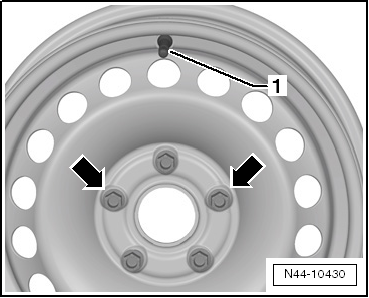
Fitting a wheel, positioning of anti-theft wheel bolts on steel wheels

Caution!
The position of the anti-theft wheel bolts relative to the tire valve on steel wheels must be observed without exception.
On steel wheels, the anti-theft wheel bolt may only be fitted to the right or left of the valve -1- (arrows).
Only if the anti-theft wheel bolt is installed in this position can the wheel trim cap be securely fitted to the steel wheel.