Tyre fitting
Break tyre beads free
- Unscrew valve insert.

Note
- If fitted, handle adhesive wheel trims carefully. The surface scratches easily.
- If the wheel trim is damaged, replace the rim.
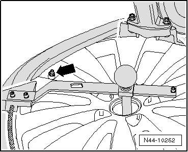
- Place bead breaker shovel -1- opposite the tyre valve -arrow- and max. 2 cm from the rim flange.
- Remove balance weights and coarse dirt from the rim.
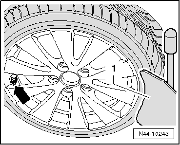
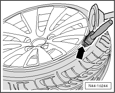
- Break both tyre beads free all the way round and apply plenty of tyre mounting paste between the tyre and rim flange -arrow-.

Note
Avoid hard braking and acceleration during the first 100 to 200 km. Otherwise the tyres may twist on the rim due to the tyre mounting paste.
Remove tyre sealant
- Place the wheel on a level surface.
- Unscrew valve insert.

Caution!
Tyre sealant is harmful to health.
Can cause eye and skin irritation and allergies.
- Wear protective gloves.
- Wear safety goggles.
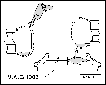
- Carefully drill a hole in the shoulder area of the tyre using a drill or milling cutter.
- Hold the wheel over a drip tray and let the sealant drain out.
- Pull the tyre off the rim.
- Clean the rim.
Removing tire
Remove tyre, wheels without and with tyre pressure monitoring
- If fitted, check the tyre pressure sensor with the vehicle diagnostic tester and replace it if necessary.

Note
- When cleaning the wheel (rim), the tyre pressure sensor (if fitted) must not come into contact with water or be blown off with compressed air.
- If fitted, handle adhesive wheel trims carefully. The surface scratches easily.
- If the wheel trim is damaged, replace the rim.
- Place the wheel with tyre on the tyre changer.
- Turn the wheel until the tyre valve or tyre pressure sensor is at least 30º before the mounting head.
- Lever the upper tyre bead over the mounting finger with the tyre lever.
- Remove the tyre lever.
- Run the tyre changer clockwise until the upper tyre bead lies completely over the rim flange.
- Turn the wheel until the tyre valve or tyre pressure sensor is at least 30º before the mounting head.
- Lever the lower tyre bead over the mounting finger with the tyre lever.
- Insert the plastic mounting lever.
- Remove the tyre lever.
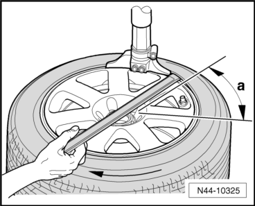
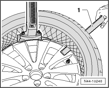
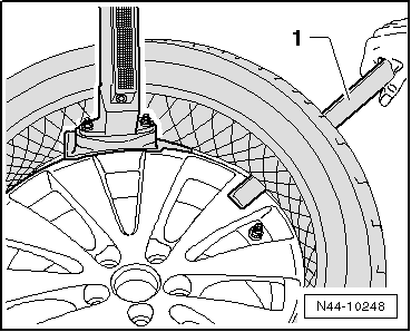
- Hold the lower tyre bead on the outside over the rim flange with the plastic mounting lever -1-, and rotate the tyre mounting machine clockwise until the tyre is completely removed from the rim.

Note
- Check the tyre pressure sensor for loose or damaged parts. If the screw connections are loose, replace the union nut, valve insert, seal, sealing washer and valve cap with new parts from the repair kit → Electronic Parts Catalogue "ETKA".
- If damaged, replace the tyre pressure sensor.
Removing tyre, run-flat tyre, ultra-high-performance tyre
- Only trained personnel may carry out mounting work on run-flat tyres and ultra-high-performance tyres.
- If fitted, check the tyre pressure sensor with the vehicle diagnostic tester and replace it if necessary.

Note
- When cleaning the wheel (rim), the tyre pressure sensor must not come into contact with water or be blown off with compressed air.
- If fitted, handle adhesive wheel trims carefully. The surface scratches easily.
- If the wheel trim is damaged, replace the rim.
- Turn the wheel until the tyre valve or tyre pressure sensor is at least 30º before the mounting head.
- Insert the hold-down clamp -3- opposite the mounting head -1- on the wheel rim.
- Lever the upper tyre bead over the mounting finger with the tyre lever.
- Remove the tyre lever.
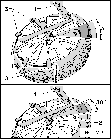
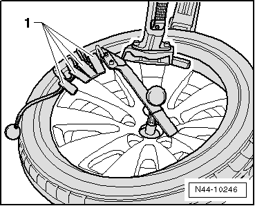
- Run the tyre changer clockwise until the upper tyre bead lies completely over the rim flange.
The hold-down clamps -1- are pushed against the mounting head in the process. This way they can be removed easily again.
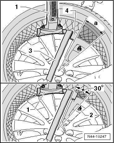
- Turn the wheel until the tyre valve or tyre pressure sensor is at least 30º before the mounting head.
- Now lever the tyre bead over the mounting finger on the mounting head with the tyre lever -3-.
- Lever the lower tyre bead over the mounting finger with the tyre lever.
- Insert the plastic mounting lever -4-.
- Remove the tyre lever -3-.
- Hold the lower tyre bead on the outside over the rim flange with the plastic mounting lever -1-, and rotate the tyre mounting machine clockwise until the tyre is completely removed from the rim.

Note
- Check the tyre pressure sensor for loose or damaged parts. If the screw connections are loose, replace the union nut, valve insert, seal, sealing washer and valve cap with new parts from the repair kit → Electronic Parts Catalogue "ETKA".
- If damaged, replace the tyre pressure sensor.
Bringing tyre to mounting temperature

Caution!
Risk of damage to the tyres from excessive heat.
- Never warm tyres with a radiant heater or hot-air blower.
- Warm the tyre with warm water or warm air (max. 50 ºC).
The optimum mounting temperature of a tyre is between 15 ºC and 30 ºC inside the tyre. The surface temperature of the tyre during the warm-up phase is not a measure of the internal temperature of the tyre.
- Store cold tyres in the workshop on an insulated base, pallet or similar for 1 day before mounting. Store the tyres individually so that they absorb the ambient air quickly.
Warm-up times for urgent cases
- Tyre with an internal temperature above 0 ºC: at least 2 h at at least 19 ºC
- Tyre with an internal temperature below 0 ºC: at least 2.5 h at at least 19 ºC
- Occasionally wipe off condensation water with a cloth.
Fitting the tyre
Fitting tyre, wheels without and with tyre pressure monitoring
- Only trained personnel may carry out mounting work on run-flat tyres.
- If fitted, check the tyre pressure sensor with the vehicle diagnostic tester and replace it if necessary.
- Bring the tyre to mounting temperature.

Note
- When cleaning the wheel (rim), the tyre pressure sensor (if fitted) must not come into contact with water or be blown off with compressed air.
- If fitted, handle adhesive wheel trims carefully. The surface scratches easily.
- If the wheel trim is damaged, replace the rim.
- Clean the rim.
- Fit a new tyre valve with valve inserter -VAS 6459-.
- Apply plenty of tyre mounting paste to the rim flanges, the tyre beads and the inside of the upper tyre beads.
- Place the inside of the tyre on the rim.
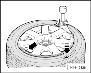
- Turn the rim until the tyre valve or the tyre pressure sensor is opposite the mounting head.
- Press the tyre into the drop centre between the tyre valve or tyre pressure sensor and the mounting head -direction of arrow-.
- Rotate the tyre mounting machine clockwise until the mounting head is in front of the tyre valve or the tyre pressure sensor. The lower tyre bead slides over the rim flange.
- Turn the rim until the tyre valve or the tyre pressure sensor is opposite the mounting head.
- Rotate the tyre mounting machine clockwise until the mounting head is in front of the tyre valve or the tyre pressure sensor. The upper tyre bead slides over the rim flange.

Caution!
Risk of damage to the rim and tyre from excessive bead-seating pressure.
Never set a bead-seating pressure above 3.3 bar.
- Inflate the tyre to a maximum filling pressure of 3.3 bar (bead-seating pressure).
- If the tyre beads do not sit fully against the rim edge, release the air, press the tyre bead again and apply plenty of tyre mounting paste to the rim flange once more.
- If the tyre beads are against the rim shoulder, increase the pressure to 4 bar.
- If the tyre beads do not sit fully against the rim shoulder, deflate the tyre, press it off and remount it.
- Screw in the valve insert.
- Inflate the tyre to the specified tyre pressure.
- Balance the wheel.

Note
Avoid hard braking and acceleration during the first 100 to 200 km. Otherwise the tyres may twist on the rim due to the tyre mounting paste.
Fitting tyre, run-flat tyre, ultra-high-performance tyre
- Only trained personnel may carry out mounting work on run-flat tyres and ultra-high-performance tyres.
- If fitted, check the tyre pressure sensor with the vehicle diagnostic tester and replace it if necessary.
- Bring the tyre to mounting temperature.

Note
- If fitted, handle adhesive wheel trims carefully. The surface scratches easily.
- If the wheel trim is damaged, replace the rim.
- Clean the rim.
- Fit a new tyre valve with valve inserter -VAS 6459-.
- Apply plenty of tyre mounting paste to the rim flanges, the tyre beads and the inside of the upper tyre beads.
- Place the inside of the tyre on the rim.
- Turn the rim until the tyre valve or the tyre pressure sensor is opposite the mounting head.
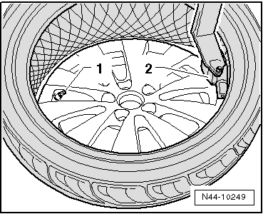
- Rotate the tyre mounting machine clockwise until the mounting head is in front of the tyre valve or the tyre pressure sensor -arrow-. The lower tyre bead slides over the rim flange.
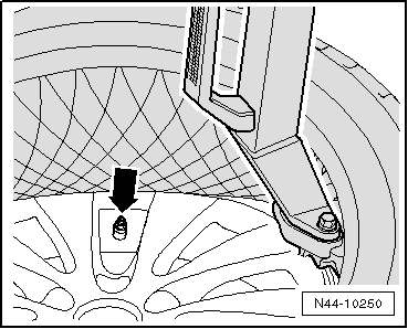
- Turn the rim until the tyre valve or the tyre pressure sensor -1- is opposite the mounting head -2-.
- Insert the hold-down clamp -3- on the rim.
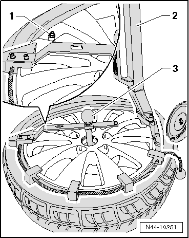
- Rotate the tyre mounting machine clockwise until the mounting head is in front of the tyre valve or the tyre pressure sensor. The upper tyre bead slides over the rim flange.
- Remove the hold-down clamp from the rim flange.

Caution!
Risk of damage to the rim and tyre from excessive bead-seating pressure.
Never set a bead-seating pressure above 3.3 bar.
- Inflate the tyre to a maximum filling pressure of 3.3 bar (bead-seating pressure).
- If the tyre beads do not sit fully against the rim edge, release the air, press the tyre bead again and apply plenty of tyre mounting paste to the rim flange once more.
- If the tyre beads are against the rim shoulder, increase the pressure to 4 bar.
- If the tyre beads do not sit fully against the rim shoulder, deflate the tyre, press it off and remount it.
- Screw in the valve insert.
- Inflate the tyre to the specified tyre pressure.
- Balance the wheel.

Note
Avoid hard braking and acceleration during the first 100 to 200 km. Otherwise the tyres may twist on the rim due to the tyre mounting paste.
Matching tyre and rim
- If necessary, remove the stand plate.
- Press the tyre off the bead seat.
- Rotate the tyre 180º relative to the rim.
- Inflate the tyre to 4 bar.
- Clamp the wheel with tyre onto the balancing machine.
- Check the radial and lateral runout of the wheel/tyre.
- If radial and lateral runout are within the specified values, balance the wheel to 0 g.
- If radial and lateral runout are outside the specified values, match the rim and tyre again and rotate the tyre 90º relative to the rim.
- Check the radial and lateral runout of the wheel/tyre again.
- If radial and lateral runout are within the specified values, balance the wheel to 0 g.
- If radial and lateral runout are outside the specified values, match the rim and tyre again and rotate the tyre 180º relative to the rim.
- Check the radial and lateral runout of the wheel/tyre again.
- If radial and lateral runout are within the specified values, balance the wheel to 0 g.
- If radial and lateral runout are still outside the specified values, check the radial and lateral runout of the rim.
- If the radial and lateral runout of the rim is within the specified values, replace the tyre.
Balancing the wheel
Balancing wheel, balancing wheel on stationary balancing machine
The following conditions must be met before you begin balancing.
- The tyre pressure must be correct.
- The tyre tread must not be worn unevenly. The tyre tread should be at least 4 mm deep.
- The tire must not have any damage, such as cuts, punctures, foreign objects, etc.
- The wheel suspension and steering, including shock absorbers, must be in perfect condition.
- Test drive carried out.

Note
- If fitted, handle adhesive wheel trims carefully. The surface scratches easily.
- If the wheel trim is damaged, replace the rim.
- use only the clamping plate for wheel type -VAS 6652- and pressure bolt -VAS 6652/1-.
Clamping the wheel onto the balancing machine
Dirt and rust on the contact surfaces and centering of the wheel will distort the result.
- Clean the contact surface, the centring and the wheel disc, for example with the pneumatic brush spray gun set -VAS 6446- → ServiceNet; Workshop Equipment, catalogue before clamping the wheel onto the balancing machine!

Note
The correct centering and clamping system must be used on the wheel balancing machine. Before starting work, refer to the corresponding centering system for wheel balancing machines → ServiceNet; Workshop Equipment, Catalog.
- Clamp the wheel with tire onto the balancing machine.

Note
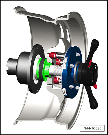
- To clamp the wheel, for example use the wheel balancing machine centering system -VAS 5271-.
- This enables 100% centering of the wheel and gentle clamping!
- Conical clamping elements do not allow 100% centering on the balancing machine.
- An off-center deviation of 0.1 mm results in an imbalance of 10 grams on the wheel/tire.
Procedure for balancing the wheel/tire
- Let the wheel/tire rotate on the balancing machine.
- Check the course of the sidewall markings near the rim flange.
- Check the tire tread pattern while the wheel/tire is rotating.

Note
If there is uneven wear, flat spots from braking, or heavy cupping, balancing cannot achieve smooth running. In this case, replace the tire.
- Check the wheel/tire for runout. If the wheel with tire runs out of round although there is no flat spot, radial runout or lateral runout may be the cause.
- Check the wheel with tire for radial runout and lateral runout.
- If radial and lateral runout are within the permissible tolerance, balance the wheel and tire.

Note
- No more than 60 grams of weight should be used per wheel.
- If more weight is required, you may be able to achieve smoother running by match mounting. Match mount tire.
- The display on the balancing machine should show 0 grams.
- As an alternative to matching, you can use the vibration control system -VAS 6230 A-.
- Bolt the wheel onto the vehicle.

Caution!
On ceramic brakes, the wheel must not be allowed to drop onto the brake disc, as this will destroy it. To remove/install the wheel, turn the long installation pin into the top position (12 o'clock) instead of the wheel bolts, and insert the short installation pin into the wheel bolt holes for support. This allows the wheel to slide over the installation aids when removing/installing it.
- Tighten the bottom wheel bolt by hand, then to approx. 30 N·m.
- Tighten the remaining wheel bolts in a crisscross pattern to approx. 30 N·m as well. This centers the wheel on the wheel hub.
- Lower the vehicle onto its wheels.
- Using the torque wrench, tighten the wheel bolts in a crisscross pattern to the specified tightening torque.
- Carry out road test.
If vibration is still felt during the road test, this may be caused by tolerances present in the wheel centering.
In unfavorable cases, component tolerances of wheels and wheel hubs can add up. This can also cause vibration. These can be eliminated with a fine balancer.
Balancing wheel, balancing wheel with fine balancer (finish balancer)
The following conditions must be met before you begin balancing.
- The tyre pressure must be correct.
- The tyre tread must not be worn unevenly. The tyre tread should be at least 4 mm deep.
- The tire must not have any damage, such as cuts, punctures, foreign objects, etc.
- The wheel suspension and steering, including shock absorbers, must be in perfect condition.
- Test drive carried out.

Note
- If fitted, handle adhesive wheel trims carefully. The surface scratches easily.
- If the wheel trim is damaged, replace the rim.
- use only the clamping plate for wheel type -VAS 6652- and pressure bolt -VAS 6652/1-.

Note
- Working with a fine balancer requires instruction from the device manufacturer.
- For balancing, place the wheels of the driven axle onto the sensor stands. With front-wheel drive, the front wheels must be placed on them, and with all-wheel drive, all 4 wheels must be placed on them.
If, when balancing on the vehicle, you determine that the residual imbalance is more than 20 grams, you should turn the wheel on the wheel hub.
- Mark the position where the imbalance is indicated.
- Then loosen the wheel and turn it on the wheel hub so that the marked position points downward.

Note
The wheel hub must not turn during this process.
- First tighten the bottom wheel bolt hand-tight, then with approx. 30 N·m.
- Now tighten the remaining wheel bolts, also in a crisscross pattern, to approx. 30 N·m. This centers the wheel well on the wheel hub.
- Check again with the fine-balancing unit whether the imbalance is less than 20 grams.

Note
The unbalance should in any case be less than 20 grams before you change the balancing weight.
- If necessary, loosen the wheel bolts again.
- Turn the wheel relative to the wheel hub again by 1 or 2 wheel bolt holes.
- Tighten the wheels using the method described above.

Note
Only when the unbalance is less than 20 grams should the unbalance be reduced by changing the balancing weight.
- Balance the wheels to under 5 grams of imbalance.
- If not already done, tighten the wheel bolts to the specified tightening torque.
Always tighten the wheel bolts with a torque wrench to the specified tightening torque.
Balancing wheel, check wheel/tire for radial runout and lateral runout
The following conditions must be met before you begin balancing.
- The tyre pressure must be correct.
- The tyre tread must not be worn unevenly. The tyre tread should be at least 4 mm deep.
- The tire must not have any damage, such as cuts, punctures, foreign objects, etc.
- The wheel suspension and steering, including shock absorbers, must be in perfect condition.
- Test drive carried out.
Radial and lateral runout is caused by inexact concentricity of the wheel and tire.
For technical reasons, 100% concentricity is not possible.
For this reason, the manufacturer permits a precisely defined tolerance for these components.
If the wheel and tire are positioned unfavorably relative to each other, this may be the cause of exceeding the maximum permissible tolerance for the wheel with tire.
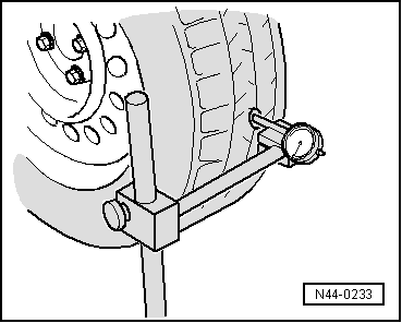
Checking Lateral Runout
- Preload the dial gauge by approx. 2 mm.
- Place the tire dial indicator against the side surface of the tire.
- Turn the wheel slowly.
- Note the smallest and the largest needle deflection.

Note
If the difference is greater than 1.3 mm, the lateral runout is too large.
In this case, the radial runout can be reduced by match mounting.
Peak deflections of the dial gauge caused by small unevenness in the rubber do not need to be taken into account.
Checking Radial Runout
- Preload the dial gauge by approx. 2 mm.
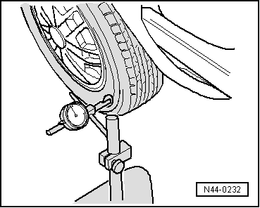
- Place the dial gauge on the tread of the tire.
- Turn the wheel slowly.
- Note the smallest and the largest needle deflection.

Note
If the difference is greater than 1 mm, the radial runout is too large.
In this case, the radial runout can be reduced by match mounting.
The table shows the maximum permissible tolerance values for the wheel with the mounted tire.
Tolerance values for radial runout and lateral runout of the rim with tire

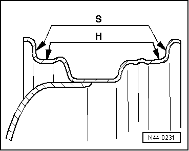
Balancing wheel, check rim for radial runout and lateral runout
- Clamp the rim onto the balancing machine.
- Use the centering system for wheel balancers -VAS 5271-.
- Preload the dial gauge by approx. 2 mm.
- Rotate the rim slowly.
- Note the smallest and the largest needle deflection.
- S - Lateral runout
- H - Radial runout
- Compare the determined value with the nominal values in the table.

Note
Peak deflections of the dial gauge caused by small unevenness do not need to be taken into account.
Nominal values for radial runout and lateral runout of the rim


Note
If the measured value exceeds the nominal value, acceptable smoothness of running cannot be achieved.