Heater Blower
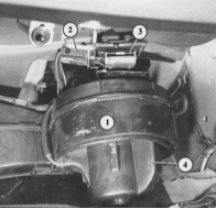
If the glove box is open or removed, the blower motor (4) becomes accessible. It is inserted from below into the air duct (1). The resistors and thermal switch (3) shown in the illustration are removed together with the connector (2). During installation, make sure the resistor block does not compromise the airtightness of the air duct. If necessary, apply sealant.
The blower motor has four speeds, which are selected by turning the "Air Supply and Blower" control on the instrument panel. Blower speed is changed by connecting resistors with different resistance values (or by switching them in series one after another). The resistors are connected to the wire leading to the body ground ("earth") on the blower motor. The power supply (through the fuse) therefore remains constant; only the ground contact "improves" or "deteriorates".
Blower Motor Troubleshooting
PROCEDURE
If the blower does not operate in any switch position, first check the corresponding fuse (see the tables in the Body Electrical System chapter).
If the wipers also do not operate despite a good fuse, the cause is the load relief relay for contact X (see the Body Electrical System chapter).
Blower motor check: open the glove box, gently pull the glove box stop latches downward and lift the box over the edge of the instrument panel. This allows the glove box to be fully folded down.
Disconnect the two-pole connector from the blower motor. Connect auxiliary wires to the two free connector terminals: from the battery positive terminal to the terminal where the black-blue wire was, and from the battery negative terminal to the terminal where the brown-red wire was.
If the blower motor is good, it should run at maximum speed. Otherwise, replace it.
If the blower does not operate at all speeds, one of the resistors may be faulty.
Remove the additional resistors and perform a visual inspection. If one of the resistors has burned out, the entire resistor block must be replaced.
If the additional resistors are good, then in addition to a broken wire, the cause of the fault may be the rotary control on the instrument panel. Replace the heater control assembly completely.
Removal of Cabin Blower Motor
The cabin blower motor is balanced together with the impeller, so only both parts can be replaced as a set.
PROCEDURE
Remove the glove box completely.
The cabin blower motor is inserted from below into the heater air duct.
Press the retaining tab on the edge of the housing with a screwdriver, turn the blower housing in the air duct to the right (clockwise) and remove it.
Remove any debris that has accumulated in the air duct.
Removal of Resistors
PROCEDURE
Remove the glove box (see Interior section).
Unscrew the Phillips-head screws under the resistor frame (where present).
Press the retaining clip down and pull the frame downward.
During installation, make sure the frame sits firmly in the air duct.
Test yourself
A quick Audi 80 quiz: every answer comes with an explanation and a link to the manual page.