Operating principle
AIRBAG CONTROL UNIT
The airbag ECU performs the following functions:
- frontal, side and rear impact detection,
- firing of the airbags and pyrotechnic seat belt pretensioners,
- storage of firing energy for the frontal igniters in case of power loss at the moment of impact,
- management of degraded operating modes,
- customer information on system faults,
- self-diagnosis of all system components,
- diagnosis / storage of the system configuration status,
- customer information on the activation / deactivation status of the passenger frontal airbag.
IMPACT DETECTION
The electronic accelerometer located in the housing detects frontal and rear impacts.
A safety sensor prevents firing in the event of a fault in the electronic accelerometer and/or the airbag ECU.
The two side airbag crash sensors, operational within 4 seconds of the key being moved to the +APC position, continuously measure lateral deceleration and inform the airbag ECU.
AIRBAG DEPLOYMENT
Principle
The electronic accelerometer measures vehicle deceleration. When the deceleration reference value is exceeded, an explosive primer ignites the booster charge, then the solid propellant. The propellant turns into gas (nitrogen), which inflates the airbag. After a few milliseconds, the airbag deflates.
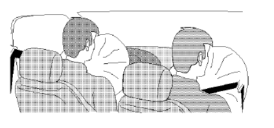
Airbag deployment
Note: The system must be repaired via the network after a pyrotechnic element has been triggered.
Deployment conditions
Deployment depends only on the presence of +apc. After the +apc supply is lost, firing of the igniters (even in the event of an impact) is inhibited after one minute.
Impact zone triggering the airbags
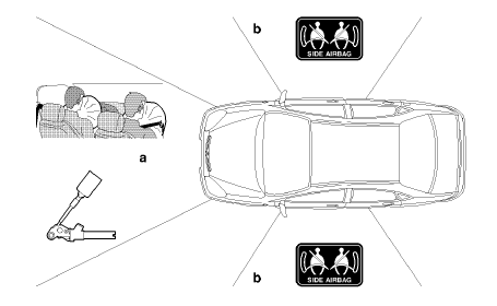
Impact zone triggering the airbags
- Deployment zone for the front airbags
- Deployment zone for the side airbags and the curtain airbags
Front airbag deployment
In the event of a severe frontal impact, the airbag control unit deploys the front airbags.
Note: Deployment of the front airbags triggers deployment of the pyrotechnic pretensioner seat belts.
Side airbag and curtain airbag deployment
On receipt of lateral deceleration data from the side airbag deployment sensors, the airbag control unit orders deployment of the side airbags and the curtain airbags.
Pyrotechnic pretensioner seat belt deployment
Deployment of the pyrotechnic pretensioner seat belts is required for any airbag deployment. In the event of a low-severity impact, the seat belts may be deployed alone.
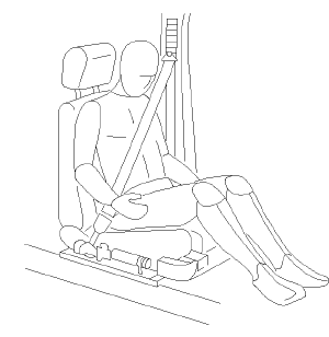
Pyrotechnic pretensioner seat belt deployment
Airbag control unit / BSI dialogue
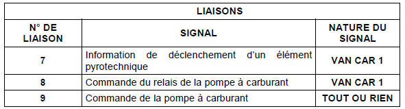
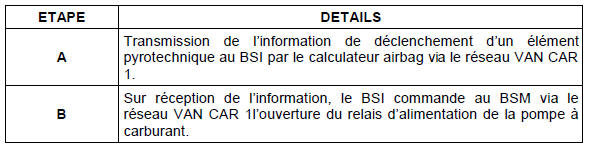
In the event of an impact, the airbag control unit sends pyrotechnic element deployment information to the BSI. This frame also indicates the corresponding pyrotechnic element(s) fired.
The BSI uses this information for the following functions:
- fuel pump cut-off,
- automatic activation of the hazard warning lights.
Degraded modes
If one of the pyrotechnic elements fails, the remaining pyrotechnic elements remain operational and can be deployed.
If the electronic accelerometer of the airbag control unit fails, all pyrotechnic elements are deactivated.
If the passenger airbag deactivation switch fails, the passenger airbag is deactivated.
If one of the side airbag deployment sensors fails, the corresponding side airbags are deactivated.
For all these failure cases, the corresponding fault is stored in the airbag control unit.
The fault warning light must remain on until the fault clears.
LOCKED MODE
After the airbags have been deployed, the airbag control unit switches to locked mode. Pyrotechnic element deployment information is stored. Faults cannot be erased under any circumstances.
INFORMATION FOR THE DRIVER
Airbag control unit fault
Block diagram
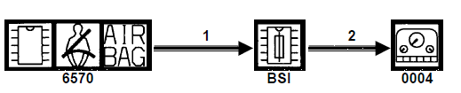
Driver information: airbag control unit fault
Key:
- triple arrow: Multiplexed link.

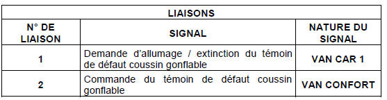
Functional description
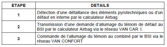
Passenger airbag deactivation
Function
The passenger airbag deactivation indicator lets the user know the operating status of the passenger airbag.
The deactivation status is read by the airbag control unit, which manages deactivation.
The passenger airbag deactivation principle consists of an impedance switch across 2 inputs of the airbag control unit, via a key-operated switch.
Block diagram

Passenger airbag deactivation
Key:
- single arrow: Wired link,
- triple arrow: Multiplexed link.
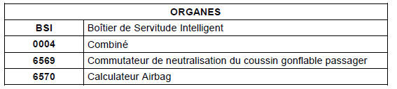
LINKS |
||
| LINK NO. | SIGNAL |
SIGNAL TYPE |
| 3 | State of the passenger airbag deactivation switch | ON/OFF |
| 4 | Request to switch the passenger airbag operating status indicator on / off | VAN CAR 1 |
| 5 | Control of the passenger airbag operating status indicator | VAN CONFORT |
| 6 | Request to deactivate the passenger airbag | VAN CAR 1 |
Functional description of passenger airbag deactivation
| STEP | DETAILS |
| 1 | Acquisition of the passenger airbag deactivation switch state by the airbag control unit |
| 2 | Transmission of the passenger airbag deactivation switch state to the BSI by the airbag control unit via the VAN CAR 1 network. |
| 3 | The BSI commands the indicator to light on the instrument cluster via the VAN CONFORT network as long as the passenger airbag deactivation switch is in the deactivated position. |
Note: The passenger airbag may be deactivated in the event of a failure of one of the networks.
Degraded modes
Switch failure
If the passenger airbag deactivation switch fails:
- the passenger airbag is deactivated,
- the BSI commands the instrument cluster to light the airbag fault and passenger airbag deactivated warning lights,
- a fault is stored in the airbag control unit.
Loss of VAN CAR 1 communication (BSI / airbag control unit)
If the VAN CAR 1 network fails:
- The passenger airbag is deactivated,
- the BSI commands the instrument cluster to light the airbag fault and passenger airbag deactivated warning lights,
- a fault is stored in the airbag control unit.
Note: After communication between the BSI and the airbag control unit is restored, the airbag control unit keeps the passenger airbag deactivated and keeps the warning lights on until the next ignition off and on cycle.
Loss of VAN CONFORT communication (BSI / instrument cluster)
If the VAN CONFORT network fails:
- The instrument cluster lights the airbag fault and passenger airbag deactivated warning lights,
- The BSI sends a passenger airbag deactivation command to the airbag control unit, which then deactivates the passenger airbag.
Note: After communication between the instrument cluster and the BSI is restored, the BSI may cancel the deactivation command, but the airbag control unit keeps the passenger airbag deactivated and keeps the warning lights on until the next ignition off and on cycle.
FUEL PUMP CUT-OFF FUNCTION
Performance
This function cuts power to the main fuel pump in the event of an impact.
Block diagram

Fuel pump cut-off function
Key:
- single arrow: Wired link,
- triple arrow: Multiplexed link.
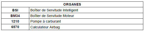
Functional description
Note: The fuel pump is permitted to operate when the key is in the +APC position (after ignition off).
Note: Cutting the fuel pump also cuts the auxiliary burner fuel pump on equipped vehicles.
Test yourself
A quick Citroen C5 Aircross quiz: every answer comes with an explanation and a link to the manual page.