Driveshafts Assembly
GENERAL INFORMATION
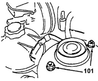
Strut Upper Mount to Body Attachment
101. STRUT UPPER MOUNT NUTS. TORQUE 30 N·m.

Bearing Race Compressing Tool
A. OUTER DIAMETER 40 MM.
B. INNER DIAMETER 20 MM.
501. BRAKE DISC.
502. NUT.
503. WASHER.
504. BOLT, 100 MM LONG.
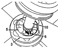
Snap Ring
3. SEPARATOR
5. BALL
6. CIRCLIP
10. SHAFT
Remove or disconnect
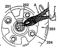
Axle Shaft Nut at Hub

Ball Joint Removal from Strut Bearing Support
7. CLAMP.
8. BOOT
10. SHAFT
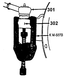
Ball Joint Stud Removal from Strut Steering Knuckle Arm
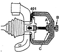
Axle Shaft Removal from Wheel Hub A. NUT.
B. BOLT.
C. THRUST BEARING.
401. WHEEL HUB
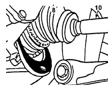
Driveshaft Removal from Transaxle Case
8. BOOT
10. SHAFT
PROCEDURE.
1. Open the hood and loosen the strut upper mount nuts.
2. Remove the wheel cap and loosen the wheel bolts.
3. Remove the cotter pin, the axle shaft nut and the washer.
4. Raise the vehicle and remove the wheel.
5. Remove the snap ring and the ball joint stud nut from the control arm.
6. Separate the control arm ball joint using puller KM-507B.
Warning.
When using puller KM-507B to remove ball joints, do not
pay attention to the marking "THIS SIDE TOWARD WHEEL" stamped on the tool..
7. Remove the ball joint stud nut from the tie rod end.
8. Separate the tie rod ball joint using puller KM-507B.
9. Pull the axle shaft out of the wheel hub.
Warning.
After removing the axle shaft from the wheel hub, the driveshaft must not hang freely,
supported only by the inner joint. Secure the free end of the driveshaft.
Place a drain pan under the driveshaft to catch leaking oil. After removing the shaft,
plug the opening in the transaxle case to prevent oil leakage and the entry of dirt into the case.
10. Driveshaft Assembly.
Warning.
After the vehicle has been driven a considerable distance (approximately 80,000–100,000 km), replace
the left and right driveshaft assemblies.
When installing, the snap ring of the lower control arm ball joint must be
replaced with a new one.
Make sure the seal in the transaxle case opening and the bearing surfaces are clean.
Installation
PROCEDURE.
1. Carefully insert the inner driveshaft stub shaft of the driveshaft 10 into the transaxle case opening, taking care not to damage the seals. Pull on the outer joint housing to check that the driveshaft stub shaft is correctly seated in the case.
2. Insert the outer driveshaft stub shaft into the wheel hub bore.
3. Install the lower control arm ball joint into the strut bearing support.
4. Install the tie rod ball joint into the strut steering knuckle arm. Tighten the nut
to the tie rod joint attachment torque of 60 N·m.
5. Thread the nut onto the control arm ball joint stud. Tighten the nut
to the control arm ball joint torque of 70 N·m.
6. Install the washer and nut onto the axle shaft stub. Do not tighten fully. Use only a new nut.
7. Install the wheel and secure it with the bolts. Do not tighten the bolts fully.
8. Lower the vehicle to the floor.
9. Tighten the wheel bolts to a torque of 90 N·m.
10. Tighten the axle shaft nut initially to a torque of 100 N·m, then
loosen the nut and retighten it to a torque of 20 N·m. Then tighten the nut a final 1/4 turn.
11. Tighten the strut upper mount to body nuts to a torque of 30 N·m.
12. Install a new cotter pin in the axle shaft nut.
13. Install the snap ring on the control arm ball joint nut.
14. Install a cotter pin in the tie rod ball joint nut (if equipped).
15. Top up the transaxle case oil to the specified level.
Test yourself
A quick Daewoo Nexia quiz: every answer comes with an explanation and a link to the manual page.